


56
The UPS outputs are each connected with the parallel
operation busbar via an isolator. The instructions from
chapter 5 apply here too.
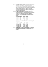
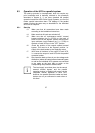
The following always holds true for the UPS input and output
conductors: The difference in length in conductors up to 20 m
per UPS can be max. 20% and max. 10% for lengths > 20 m
per UPS.
The jumper installed between “JP1” and “JP2” on the
connection panel of every UPS at the factory must be removed.
The UPS output distribution also has to take place according to
the instructions in chapter 5. In particular, make sure that the
individual switching elements are correctly labelled, in order to
prevent operating errors later as well. The communication of
the units switched in parallel takes place via the 25-pin parallel
operation cable(s) included in the scope of delivery.
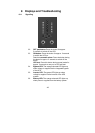
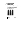
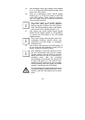
For this purpose, first remove the parallel port covers
(no. 5, p. 27/28) and connect the UPS units with each other with
one parallel operation cable each. Use one
parallel operation
cable for 2 units and two parallel operation cables for 3 units (do
not create a ring structure!).
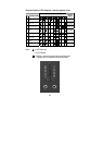
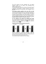
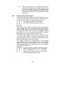
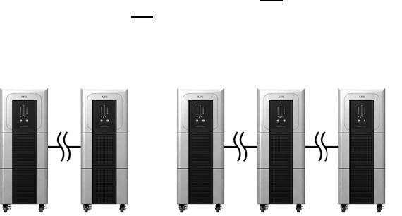
(Communicative) parallel operating connection
... for 2 units:
... for 3 units:
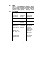
After connecting the parallel operation cables, fasten the
previously removed parallel port covers. Turn these by 180° so
that the slot of the cover is facing downwards.
The hardware-related installation is now complete.