


1-45
Making Measurements
Measuring Electrical Length and Phase Distortion
The measurement value that the analyzer displays represents the electrical length of
your device relative to the speed of light in free space. The physical length of your device
is related to this value by the propagation velocity of its medium.
NOTE Velocity factor is the ratio of the velocity of wave propagation in a coaxial
cable to the velocity of wave propagation in free space. Most cables have a
relative velocity of about 0.66 the speed in free space. This velocity depends
on the relative permittivity of the cable dielectric (ε
r
) as
You could change the velocity factor to compensate for propagation velocity by
pressing (enter the value) . This
will allow the analyzer to accurately display the equivalent distance that
corresponds to the entered electrical delay.
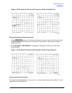
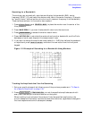
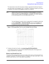
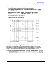
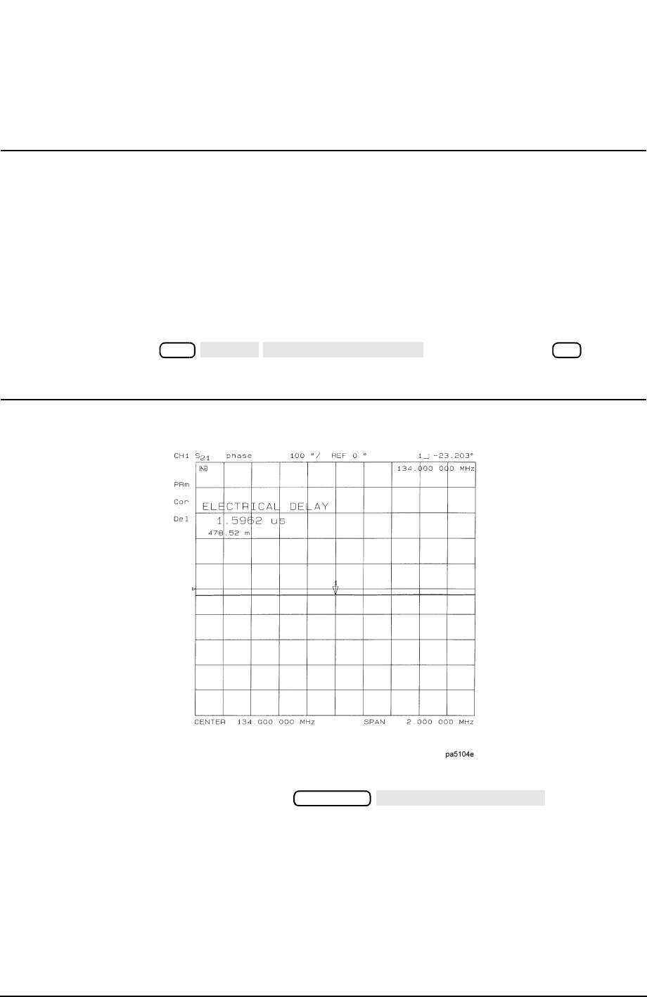
Figure 1-35 Example Best Flat Line with Added Electrical Delay
8. To display the electrical length, press .
In this example, there is a large amount of electrical delay due to the long electrical
length of the SAW filter under test.
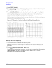
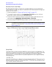
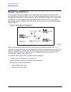
Measuring Phase Distortion
This portion of the example shows you how to measure the linearity of the phase shift over
a range of frequencies. The analyzer allows you to measure this linearity and read it in two
different ways: deviation from linear phase, or group delay.
Cal
MORE
VELOCITY FACTOR
x1
Scale Ref
ELECTRICAL DELAY