2 Agilent 34937A-34939A General Purpose Switch Modules User’s Guide
Operating Considerations.
Operating Considerations.
Electrical Considerations
See the Introduction to the Plug In Modules chapter of the 34980A
Mainframe User’s Guide for detailed environmental operating conditions
for the 34980A mainframe and its installed modules. That guidance sets
maximum per channel current and power ratings at rated voltage for
pollution degree 1 (dry) and pollution degree 2 (possible condensation)
conditions, for each of the GP modules.
Temperature Sensor
A temperature sensor on these modules triggers system interrupts when
high-carry current-induced heat on the modules is excessive and sets the
HOT annunciator on the front panel. This over-temperature situation
generates an SRQ event when the factory- set 70
o
C threshold is reached. It
is up to the user to determine what, if any, action should be taken.
Switching Reactive Loads
Reactive loads (those that include significant inductance or capacitance)
can cause voltage spikes or current spikes during switching operations.
The general purpose modules are designed for switching reactive loads.
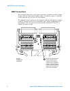
The optional 34937T and 34938T terminal blocks have solder pads for
adding snubber circuits for the 5 A relays to reduce the reactive
transients. See the drawings on page 8 and page 11 for the locations of
snubber circuit pads and installation information about a snubber circuit.
Hardware Power-Fail Jumper
A hardware jumper on the 34937A and 34938A modules allows you to
define the power-failure states for the modules’ 5 A latching relays.
Depending on the position of the jumper, the 5 A relays will either open
or maintain state when system power failure occurs.
On the 34939A module, a hardware jumper allows you to define the
power- failure state affecting all 64 of the module’s 1 A latching relays.
Depending on the position of the jumper, these relays will either open or
maintain state when system power failure occurs.
WARNING
Do not connect either the 34937A, 34938A or 34939A module
directly to a mains power outlet. If it is necessary to switch a mains
voltage or any circuit where a large inductive load may be
switched, you must add signal conditioning elements to reduce the
potential transients before they reach the module or the Analog
Buses.


