


Operating Instructions
73
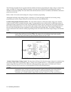
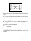
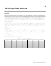
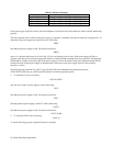
In Figure 3-21 the FLT output drives not only the INH input, but also triggers a sequential down programmer circuit. This
would allow any supply in the system to trigger the sequential down programmer (via their FLT outputs) and disable the
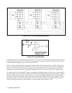
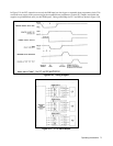
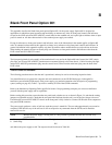
supplies in a predetermined order (via their INH inputs). Timing relationships for FLT and INH are shown in Figure 3-20.
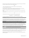
Figure 3-20. Timing Diagram
Figure 3-21. FLT & INH Example