2 - Verification and Performance Tests
12
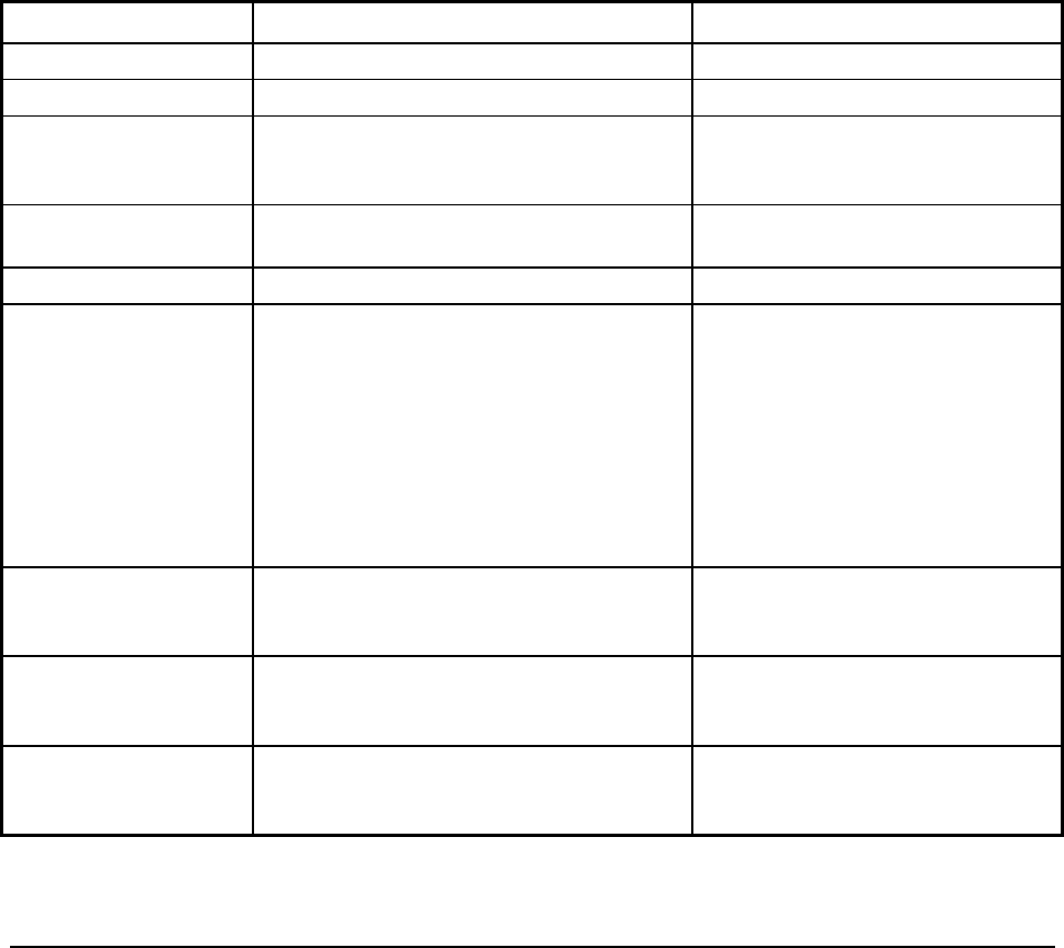
Table 2-1. Test Equipment Required for Verification and Performance Tests
Type Specifications Recommended Model
Current Monitor Resistor 15 A (0.1 ohm) 0.04% Guildline 9230/15
DC Power Supply Minimum 5 A output current rating Agilent 6632B
Digital Voltmeter Resolution: 10 nV @ 1V
Readout: 8 1/2 digits
Accuracy: 20 ppm
Agilent 3458A or equivalent
Electronic Load 100V, 5 A minimum, with transient capability Agilent 6060B (60V max.), 6063B
(240V) or equivalent
GPIB Controller Controller with full GPIB capabilities HP Series 300 or equivalent
Resistors
(Load resistors may
substitute for electronic
load if load is too noisy
for CC PARD test)
400 ohm, 5W
1 ohm, 100 W (or 2 ohm adjustable)
0.6 ohm, 100W (6611C)
9 ohm, 100W (6612C)
49 ohm, 100W (6613C)
99 ohm, 100W (6614C)
or an appropriate 150W Rheostat
Agilent p/n 0811-1857
Ohmite D12K2R0 (2 ohm adjustable)
Oscilloscope Sensitivity: 1 mV
Bandwidth Limit: 20 MHz
Probe: 1:1 with RF tip
Agilent 54504A or equivalent
RMS Voltmeter True RMS
Bandwidth: 20 MHz
Sensitivity: 100 µV
Agilent 3400B or equivalent
Variable-Voltage
Transformer
Adjustable to highest rated input voltage
range.
Power: 500 VA
Measurement Techniques
Test Setup
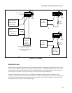
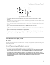
All tests are performed at the rear terminals of the supply as shown in Figure 2-1. Measure the dc voltage directly at
the +S and -S terminals. Set the Remote/Local switch to Remote and connect the output for remote sensing. Use
adequate wire gauge for the load leads.


