12 Remote Programming
Header Convention. In this manual, headers are emphasized with boldface type. The proper short form is shown in
upper-case letters, such as DELay.
Header Separator. If a command has more than one header, you must separate them with a colon. (VOLT:PROT
OUTPut:PROTection:CLEar)
Optional Headers. The use of some headers is optional. Optional headers are shown in brackets, such as
OUTPut[:STATe] ON. However, if you combine two or more message units into a compound message, you may need to
enter the optional header. This is explained under "Traversing the Command Tree."
Query Indicator
Following a header with a question mark turns it into a query (VOLT? VOLT:PROT?). If a query contains a parameter,
place the query indicator at the end of the last header (VOLT:PROT? MAX).
Message Unit Separator
When two or more message units are combined into a compound message, separate the units with a semicolon
(STATus:OPERation?;QUEStionable?).
Important You can combine message units only at the current path of the command tree (see "Traversing the
Command Tree").
Root Specifier
When it precedes the first header of a message unit, the colon becomes a "root specifier". This indicates that the command
path is at the root or top node of the command tree. Note the difference between root specifiers and header separators in the
following examples:
OUTP:PROT:DEL .1 All colons are header separators
OUTP:PROT:DEL .1 The first colon is a root specifier
OUTP:PROT:DEL .l;:VOLT 12.5 The third colon is a root specifier
Message Terminator
A terminator informs SCPI that it has reached the end of a message. Three permitted messages terminators are:
• Newline (<NL>), which is ASCII decimal 10 or hex 0A.
• End or identify (<END>).
• Both of the above (<NL><END>).
In the examples of this manual, there is an assumed message terminator at the end of each message. If the terminator needs
to be shown, it is indicated as <NL> regardless of the actual terminator character.
Traversing the Command Tree
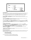
Figure 2-2 shows a portion of the subsystem command tree (you can see the complete tree in Figure 3-2). Note the location
of the ROOT node at the top of the tree. The SCPI interface is at this location when:
• The power supply is powered on.
• A device clear (DCL) is sent to the power supply.
• The interface encounters a message terminator.
• The interface encounters a root specifier.


