


NOTE: The External Trigger Output functionality is implemented in the hardware. No Trigger Out signal occurs for
software-generated triggers such as those of the AUTO mode of AcqirisLive or through the use of the function
AcqrsD1_forceTrigger. However, AcqrsD1_forceTriggerEx does generate the signal.
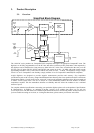
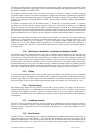
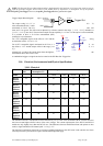
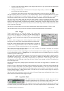
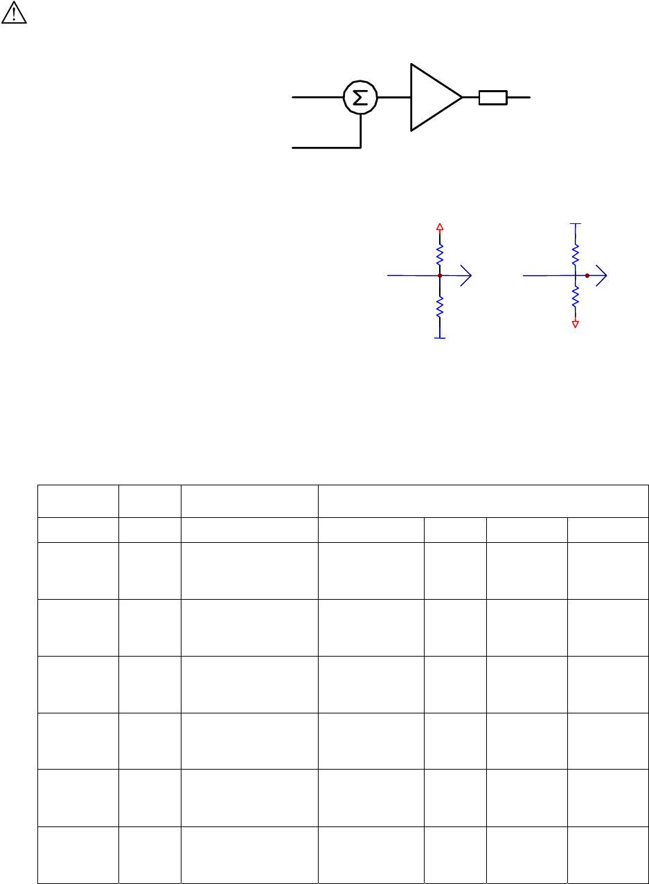
Trigger Output Block diagram:
The output swing is 1.6 V (±
0.8 V)
when unloaded and 0.8 V when
terminated on 50 Ω. The rise
and fall
times are 2.5 ns typical. The offset can be adjusted, by software control in the range [–2.3 V, +2.3 V] unloaded, or
[-1.15 V, +1.15 V] into 50 Ω. The maximum output current capability is ± 15 mA. As the output is retro-terminated,
it is possible to drive a 50 Ω line unterminated (HiZ)
without loss of performance.
Signal: 1.6V swing
0v centered
Offset: +/-2.5 V
G=1
50 Ohm
Trigger Out
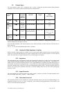
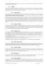
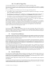
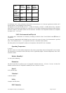
For a TTL compatible signal, set the offset to 1.0 V and the swing
at destination will be +0.2 to +1.8 V.
For an ECL compatible signal, terminated on 50 Ω to –1.2
V, set
the offset to –1.2 V and the output will be in the range [–0.8 V, –1.6
V]).
Alternatively, to reduce the current drawn from the digitizer, the
terminations shown here can be used:
A standardized trigger out signal can also be routed to the PXI Bus Star Trigger line.
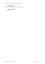
3.10. Electrical, Environmental and Physical Specifications
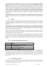
3.10.1. Electrical
PCI
Rev.
Max. Power
Consumption (W)
Current Requirements (A)
Model
+12 V +5 V +3.3 V -12 V
DC122
Default
Memory
2.2 31 0.1 3.3 3.4 0.03
DC122
Optional
Memory
2.2 40 0.1 3.3 6.0 0.03
DC152
Default
Memory
2.2 34 0.1 3.9 3.4 0.03
DC152
Optional
Memory
2.2 43 0.1 3.9 6.0 0.03
DC2x2
Default
Memory
2.2 62 0.1 6.7 7.2 0.03
DC2x2
Optional
Memory
2.2 80 0.1 6.7 12.5 0.03
The Maximum Power Consumption has been increased by 5% over the value calculated with the currents shown to
take into account higher allowed values of the crate voltages. The current requirements of the DC222 and DC252
models are only slightly lower than the DC282 case. The differences between the different front end options are also
small; a single Standard or HZ channel pulls ~0.3 A @ +5 V.
The electrical requirements shown above can impose loading limitations in the cPCI crate. In the extreme case where
a PC503 processor is present in an Acqiris crate the following limits apply:
R
68
R
220
-5V
GND
Trigger
Out
With
Offset
-1.18V
R
68
R
220
GND
+5V
ECL
Signal
TTL
signal
Trigger Out
With
Offset
+1.18V
User Manual: Family of 10-bit Digitizers Page 35 of 55