


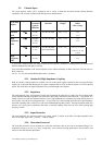

3.2. Channel Input
The 10-bit digitizer family can be configured with a variety of front-end mezzanine boards offering different
capabilities. The currently available front end options are detailed below:
Front End
Option
Impedance Bandwidth
Guaranteed
(typical)
/ Risetime
BW Limiter
selections
FS Voltage
Ranges
Maximum
Offset
/ Max. Voltage
Standard
(Std)
50 Ω
2 GHz
0.17 ns
20, 200, 700 MHz 0.05 – 5.0 V
± 5 V
±
5 V
50 Ω
950 MHz
( 1 GHz)
0.35 ns
20, 200, 700 MHz 0.05 – 5.0 V
± 5 V
±
5 V
High-
Impedance
(HZ)
1 MΩ
(300 MHz)
1.2 ns
20, 200, 700 MHz
(see remark below)
0.05 – 50 V
±
20 V (> 0.5 V FS)
± 200 V (> 5V FS)
±
300 V
High-
Frequency
(HF)
50 Ω
3 GHz
0.12 ns
1 V
± 0.5 V
±
2 V
A given unit’s model number will indicate which front end option is installed. If nothing follows the number itself
then the standard front end option is present.
Units with either Standard or HF front end options can be ordered with BNC or SMA connectors. The HZ units use
BNC connectors.
For FS > 5 V only the 20 MHz Bandwidth Limiter is available.
3.2.1. Standard & High Impedance Coupling
Both AC and DC coupling modes are available. The AC mode couples signals capacitively thus removing the input
signal’s DC component and filtering out any signal component below 16 Hz for the HZ option or 32 Hz for the Std
option. DC mode allows all signal components to be passed through to the digitizer.
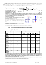
3.2.2. Impedance
The input channels of the 10-bit Digitizer Family offer termination in either 50 Ω or 1 MΩ. The 50 Ω coupling mode
for the Standard and High-Impedance front ends offers high quality termination with better than ± 1% precision. It is
ideally suited to use with 50 Ω transmission lines (coax), high bandwidth low impedance (typically 500 Ω) probes or
active probes. The HF 50 Ω coupling mode has ± 2% precision The 1 MΩ coupling mode provides a high impedance
(low load) capability that is suited for use with most standard high impedance probes. The high impedance mode also
features low (14 pF typical) capacitance that helps to minimize loading effects that can occur when probing high
frequency circuits.
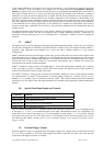
3.2.3. Input Protection
The input amplifiers are protected against over-voltage signals as shown in the table. The High-impedance limit
refers to the input signal’s DC + peak AC < 10 KHz voltage.
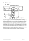
3.2.4. Mezzanine Front-end
The front-end electronics are all mounted on a removable mezzanine card. In the event of accidental damage or as
components fatigue over time (e.g. relays in high duty cycle automated testing applications), the mezzanine card
allows for fast and efficient replacement.
User Manual: Family of 10-bit Digitizers Page 28 of 55