


Agilent E5250A User’s Guide, Edition 8 4-7
Setting up Measurement Environment
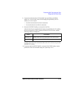
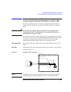
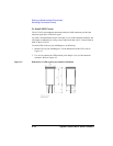
Mounting Connectors Directly
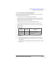
Table 4-1 Recommended Parts
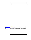
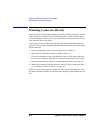
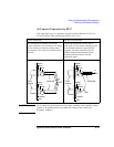
Table 4-2 Dimensions of Connector Holes
Usage
Agilent Part
No.
Description
Making interlock
circuit
1252-1419C Interlock Connector (6 pin, female)
3101-0302 or
3101-3241
Switch
1450-0641 LED (V
F
≅ 2.1 V @ I
F
= 10 mA)
8150-5680 Wire
Connecting
E5252A output
1250-2457 Triaxial Connector (female)
8121-1191 Low Noise Coaxial Cable
Connecting
E5255A output
1251-2367 Connector Frame (female)
1251-0179 Coaxial Connector (female) (8ea. required for one frame.)
0380-3070 Screw (2ea. required for one frame.)
2260-0002 Nut (2ea. required for one frame.)
2190-0913 Washer (2ea. required for one frame.)
8121-1191 Low Noise Coaxial Cable
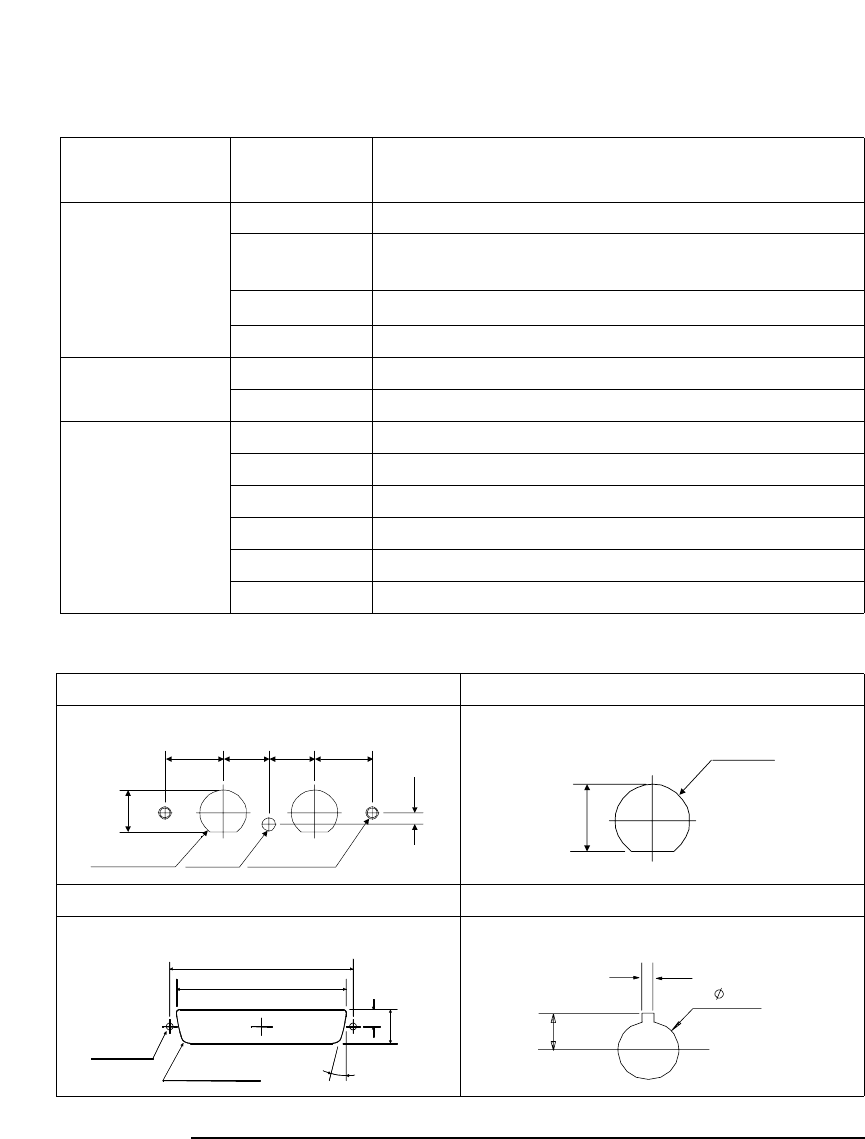
Kelvin Triaxial Connector (in mm) Triaxial Connector (in mm)
8 Channel Shielded Coaxial Connector (in mm) Interlock Connector (in mm)
2 − ∅11.3 ∅3.2 2 − M3 x 0.5
14 11 11 14
2.8
10.3
∅11.3
10.3
63.5
59
12
6
4
−
R1.5
2
−
∅
3
10
o
1.8
8.2
5
.
1