


Front Panel
LED Indicators
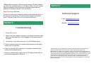
Rear Panel
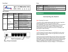
LED Color Status Description
On The switch is powered on.
PWR Green
Off The switch is powered off.
On LAN port is connected.
Off LAN port is not connected.
Green
(10/100M)
Flashing Transferring or receiving data.
On LAN port is connected.
Off LAN port is not connected.
LNK/ACT
Yellow
(10/100/100M)
Flashing Transferring or receiving data.
Ports
Item Name Description
Power Power connector, DC 12V / 1A.
1 - 5 10/100/1000Mbps LAN ports 1 to 5.
Connecting the Switch
Note: Operating Environment
This switch must be installed and operated within the limits of specified
operating temperature (32~104
0
F) and humidity (0~90%
Non-condensing). Do not place objects on top of the unit. Do not obstruct
any vents at the sides of the unit. Do not position the unit near any
heating source such as heater, radiator, or direct exposure to sun.
Prevent entering of water and moisture into the unit. If necessary, use
dehumidifier to reduce humidity.
Step 1 Connecting to network devices
The RJ-45 ports on the switch support Auto-MDI/MDI-X function which
allows using straight-through or cross-over type cables to connect this
switch to workstation or hub.
Connect one end of the network cable to the RJ-45 port on the rear panel,
and connect the other end of the network cable to the RJ-45 port on the
network device. Follow the same procedure to connect all the RJ-45 ports
of the switch. The UTP network cables must be four pairs Category 5 or
above for 1000Mbps data transmission; two pairs Category 5 for
100Mbps data transmission; two pairs Category 3, 4 or 5 standards for
Section 2