


12 505942
Installation
© Copyright, Alliance Laundry Systems LLC – DO NOT COPY or TRANSMIT
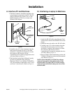
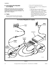
D. Connecting the Repeater
to the PC
Refer to Figure 8
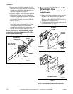
1. Attach one of the 210150 Network Cables to
segment 1 of the repeater.
2. Connect the RED and BLACK wires of that
Network Cable to the terminal strip coming
from the computer (RED to RED and BLACK
to BLACK). Do not connect the GREEN wire.
3. When repeater is used with a desktop PC, the
bias resistor in the repeaater must be removed.
Open the repeater and remove jumpers J3 and
J4. Refer to the manual included with the
repeater for specific instructions.
NOTE: Ensure that only the bias resistors that
correspond to segment one (PC connection) are
removed.
4. Connect one of the 210150 Network Cables to
segment 2 of the repeater.
5. Connect the RED and BLACK wires of that
Network Cable to the terminal strip going out to
one leg of the network (RED to RED and
BLACK to BLACK). Do not connect the
GREEN wire.
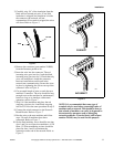
6. Terminate the last machine on this leg with a
120 Ohm 1/2 Watt resistor.
NOTE: Up to 124 nodes may be connected to any
given segment coming off the repeater. A total of
250 nodes may be connected to the network.
7. Repeat steps 4 – 6 for the remaining 2 segments
as required. There is no need to connect a cable
or a terminating resistor to an unused segment
on the repeater.
8. Connect the bayonet style connector of the wall
adapter to the 12 VDC input on the repeater.
9. Connect the wall adapter to a 120 VAC 60 Hz.
outlet.
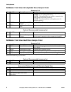
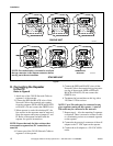
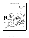
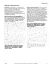
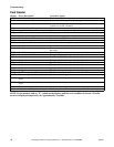
Figure 7
6
H3
LOWER
UPPER/SINGLE
54321
123456
6
H3
LOWER
UPPER/SINGLE
54321
123456
6
H3
LOWER
UPPER/SINGLE
54321
123456
CONTROL1
SINGLE UNIT
6
H3
LOWER
UPPER/SINGLE
54321
123456
6
H3
LOWER
UPPER/SINGLE
54321
123456
6
H3
LOWER
UPPER/SINGLE
54321
123456
123456123456 123456
CONTROL2
STACKED UNIT
TERMINATING
RESISTOR
NOTE: For stacked units, wire must be run from
the top connector to the bottom connector before
moving on to the next machine.