


Related Documents
For details on the features and functions of your Allied
Telesyn AT-LX3800U Multi-Service Transport System, refer
to the following documents on our web site,
www.alliedtelesyn.com:
• AT-LX3800U Multi-Service Transport System
Installation and Maintenance Guide
(part number 613-50549-00)
• AT-S65 Management Software User’s Guide
(part number 613-50604-00)
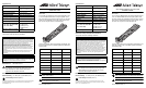
Verifying Package Contents
Make sure that the correct components are included in your
package:
• AT-LX3811/x Multi-Service Line Card
• This installation guide
• Warranty card
If any item is missing or damaged, contact your Allied
Telesyn sales representative for assistance.
Installing the Line Card
To install an AT-LX3811/x Line Card, perform the following
procedure:
1. Remove the AT-LX3811/x line card from its shipping
package and store the package in a safe place. You
must use the original package if you need to return the
unit to Allied Telesyn.
2. Select the slot in the AT-LX3800U chassis that
corresponds to the number of the line card you want to
install.
3. Remove any AT-LX3801 Blank Slot Cover from the
slot.
Keep the blank slot cover in a safe area in case you
remove the line card. The blank slot cover protects the
fiber optic connectors on the backplane from becoming
dirty, and helps maintain proper air flow through the
chassis.
4. Remove the dust caps from the fiber optic connectors
at the back of the card and save for future use.
173
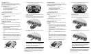
5. Locate the left and right alignment guides in the slot.
6. Align the back edge of the line card with the left and
right alignment guides.
7. Slide the card into the slot that corresponds to the line
card number, until the faceplate is flush with the front.
8. Use a Phillips head screwdriver to tighten the captive
screws on the line card.
Note
Always tighten the captive screws to secure the line
card to the chassis. This helps ensure that the fiber
optic connectors at the back of the line card are
securely connected to the backplane.
9. Repeat this procedure to install additional line cards.
For information about the line card LEDs, installing SFPs in
the line card, and connecting fiber optic cables, refer to the
AT-LX3800U Multi-Service Transport System Installation
and Maintenance Guide.
RDY
TX
RX
TRIB
SYNC
TX
RX
LINE
138
Alignment Guides
2
3
4
5
6
SFP
SYNC
TX
RX
LINE
RDY
TX
RX
TRIB
AT-LX3811/3
SFP
SYNC
TX
RX
LINE
RDY
TX
RX
TRIB
AT-LX3811/4
TRIB
RD
T
R
TRIB
X3811/2
SFP
SYNC
TX
RX
LINE
AT-LX3811/8
S
FP
S
Y
N
C
T
X
R
X
L
IN
E
R
D
Y
T
X
R
X
T
R
IB
SFP
SYNC
TX
RX
LINE
RDY
TX
RX
TRIB
AT-LX3811/6
139
2
3
4
5
6
SFP
SYNC
TX
RX
LINE
RDY
TX
RX
TRIB
AT-LX3811/3
SFP
SYNC
TX
RX
LINE
RDY
TX
RX
TRIB
AT-LX3811/4
TRIB
RD
T
R
TRIB
X3811/2
SFP
SYNC
TX
RX
LINE
SFP
SYNC
TX
RX
LINE
RDY
TX
RX
TRIB
AT-LX3811/6
SFP
SYNC
TX
RX
LINE
RDY
TX
RX
TRIB
AT-LX3811/5
140
Related Documents
For details on the features and functions of your Allied
Telesyn AT-LX3800U Multi-Service Transport System, refer
to the following documents on our web site,
www.alliedtelesyn.com:
• AT-LX3800U Multi-Service Transport System
Installation and Maintenance Guide
(part number 613-50549-00)
• AT-S65 Management Software User’s Guide
(part number 613-50604-00)
Verifying Package Contents
Make sure that the correct components are included in your
package:
• AT-LX3811/x Multi-Service Line Card
• This installation guide
• Warranty card
If any item is missing or damaged, contact your Allied
Telesyn sales representative for assistance.
Installing the Line Card
To install an AT-LX3811/x Line Card, perform the following
procedure:
1. Remove the AT-LX3811/x line card from its shipping
package and store the package in a safe place. You
must use the original package if you need to return the
unit to Allied Telesyn.
2. Select the slot in the AT-LX3800U chassis that
corresponds to the number of the line card you want to
install.
3. Remove any AT-LX3801 Blank Slot Cover from the
slot.
Keep the blank slot cover in a safe area in case you
remove the line card. The blank slot cover protects the
fiber optic connectors on the backplane from becoming
dirty, and helps maintain proper air flow through the
chassis.
4. Remove the dust caps from the fiber optic connectors
at the back of the card and save for future use.
173
5. Locate the left and right alignment guides in the slot.
6. Align the back edge of the line card with the left and
right alignment guides.
7. Slide the card into the slot that corresponds to the line
card number, until the faceplate is flush with the front.
8. Use a Phillips head screwdriver to tighten the captive
screws on the line card.
Note
Always tighten the captive screws to secure the line
card to the chassis. This helps ensure that the fiber
optic connectors at the back of the line card are
securely connected to the backplane.
9. Repeat this procedure to install additional line cards.
For information about the line card LEDs, installing SFPs in
the line card, and connecting fiber optic cables, refer to the
AT-LX3800U Multi-Service Transport System Installation
and Maintenance Guide.
RDY
TX
RX
TRIB
SYNC
TX
RX
LINE
138
Alignment Guides
2
3
4
5
6
SFP
SYNC
TX
RX
LINE
RDY
TX
RX
TRIB
AT-LX3811/3
SFP
SYNC
TX
RX
LINE
RDY
TX
RX
TRIB
AT-LX3811/4
TRIB
RD
T
R
TRIB
X3811/2
SFP
SYNC
TX
RX
LINE
AT-LX3811/8
S
FP
S
Y
N
C
T
X
R
X
L
IN
E
R
D
Y
T
X
R
X
T
R
IB
SFP
SYNC
TX
RX
LINE
RDY
TX
RX
TRIB
AT-LX3811/6
139
2
3
4
5
6
SFP
SYNC
TX
RX
LINE
RDY
TX
RX
TRIB
AT-LX3811/3
SFP
SYNC
TX
RX
LINE
RDY
TX
RX
TRIB
AT-LX3811/4
TRIB
RD
T
R
TRIB
X3811/2
SFP
SYNC
TX
RX
LINE
SFP
SYNC
TX
RX
LINE
RDY
TX
RX
TRIB
AT-LX3811/6
SFP
SYNC
TX
RX
LINE
RDY
TX
RX
TRIB
AT-LX3811/5
140