


Hardware Reference 7
C613-03022-00 REV K
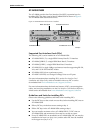
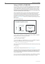
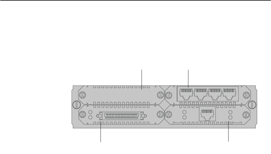
AT-AR040 NSM
The AT-AR040 provides four Port Interface Card (PIC) expansion bays for
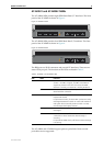
installing PICs. The front panel of the AT-AR040 NSM is shown in Figure 2.
The AT-AR040 NSM does not have LEDs.
Figure 2: AT-AR040 NSM with three PICs installed
Supported Port Interface Cards (PICs)
The following PICs can be installed in an AT-AR040 NSM:
■ AT-AR020 PRI E1/T1, a single ISDN Primary Rate E1/T1 interface
■ AT-AR021(S) BRI-S/T, a single ISDN Basic Rate S/T interface
■ AT-AR021(U) BRI-U, a single ISDN Basic Rate U interface
■ AT-AR023 SYN, a single 2Mbps synchronous interface supporting RS-232,
X.21, and V.35 in DTE and DCE modes
■ AT-AR024 ASYN4, four asynchronous ports
■ AT-AR027 VoIP-FXS, two Foreign Exchange Voice over IP ports
For more information about installing PICs, see the Port Interface Card
Installation and Safety Guide, which is included with every PIC or can be
downloaded from www.alliedtelesis.com/support/software.
For more information about the hardware features of PICs, constructing data
cables, and verifying installation, see the Port Interface Card Hardware Reference,
which can be downloaded from www.alliedtelesis.com/support/software.
Guidelines and limits for installing PICs
Observe the following guidelines and limits when installing PICs:
■ Use the PIC bays on the switch or router first, before installing PICs into an
AT-AR040 NSM.
■ Fill any PIC bays in the base router starting at bay 0.
■ Fill the PIC bays in the AT-AR040 NSM starting at bay 0.
■ You can install a maximum of two AT-AR020 PRI E1/T1 PICs into an
AT-AR040 NSM, and maximum of four total in a switch or router.
■ If two AT-AR020 PICs are installed in an AT-AR040 NSM, PIC one must be
installed in the lower row (bay 0 or 1) and the other PIC must be installed
in the upper row (bay 2 or 3).
nsm4pic3
ASYN
30
SYN
Tx
Rx
AT-A R023 SYN PIC
Blank face-plate
AT-A R020 PRI E1/T1 PIC
AT-A R
024 ASYN4 PIC
Active
D Data
B Data
PRI E1/T1
N
T