


Installation
12
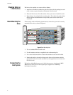
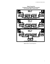
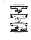
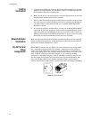
Before using the 100Base-TX module, prepare Category 5 straight-through
twisted-pair cable with RJ-45 plugs at both ends. When connecting the module
directly to an end-node device (e.g., a workstation or file server), a bridge or router,
run cable from the MDI-X port on the uplink module to the target device. However,
when connecting the module to a compatible hub or switch, connect one end of the
cable to the MDI port on the uplink module, and the other end to an MDI-X port on
the target device (or vice versa). When inserting an RJ-45 plug, be sure the tab on
the plug clicks into position to ensure that it is properly seated. Note that as a
general rule, the length of any twisted-pair cable should not exceed 100 meters
(328 feet).
Note
In the present design, the uplink port only can not be monitored or managed by
Local Management Agent, Telnet Agent, RMON Agent, SNMP Agent, or Web-
based Management.
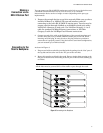
Powering ON the
Hub
1. Plug the power cord into the power socket at the rear of the hub, and the other
end into a power outlet.
2. Check the LED marked Power ON the front panel to see if it is ON. The unit
will automatically select the setting that matches the connected input voltage.
Therefore, no additional adjustments are necessary when connecting it to any
input voltage within the range marked on the rear panel.
3. The hub performs a self-diagnostic test upon power-on. (Note that this test
takes about 10 seconds to complete.)
4. However, remember that the optional slide-in modules are not hot-swappable.
Be sure the hub is powered OFF when installing or removing these modules.
5. A socket is provided on the back of the hub for a redundant power unit (RPU)
which will supply power to the hub in the event that its internal power supply
should fail. Refer to the manual provided with the RPU for further details.