


8 SwitchBlade Chassis and Fan Tray
C613-04029-01 REV C
Follow these steps to install a fan tray:
1. Read the safety information
The SwitchBlade Safety and Statutory Information booklet includes all
relevant safety information. A copy of the safety booklet is supplied with
each fan tray. A PDF version can be found on the CD-ROM that ships with
every switch controller and every chassis, or can be downloaded from
www.alliedtelesyn.co.nz/support/switchblade/.
2. Gather the tools and equipment you will need
To loosen or secure a fan tray you will need a Phillips #2 screwdriver.
3. Prepare the fan tray
In an antistatic environment, remove the fan tray from its packing material.
Be sure to observe ESD precautions.
Do not attempt to install a fan tray without observing correct antistatic
procedures. Failure to do so may damage the chassis or fan tray. If you are
unsure what the correct procedures are, contact your authorised Allied Telesyn
distributor or reseller.
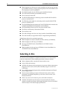
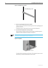
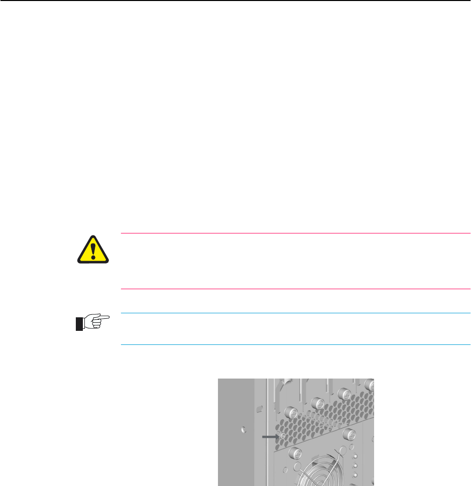
An ESD socket is provided on the front panel of the SwitchBlade chassis. The socket is
designed to be used in conjunction with an ESD wrist strap (see Figure 3 on page -8).
Figure3: ESD socket on the SwitchBlade 8 chassis.
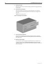
4. Detach the cable manager (for the SwitchBlade 8)
If a cable manager is attached to the fan tray’s front panel, remove it by
loosening its mounting screws and lifting it clear of the fan tray bay. If
network cables are attached, let the cable manager tilt forward, taking care
not to disturb any cable connections.
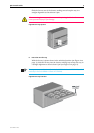
5. Remove the fan tray bay faceplate or existing fan tray
To remove a blank faceplate:
If a faceplate is attached to the chassis, use a Phillips #2 screwdriver to
loosen the faceplate’s two mounting screws until they disengage from the
chassis, then remove the faceplate.
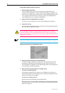
To remove an existing fan tray:
Remove the fan tray faceplate (as described above).
Release the fan tray’s two locking mechanisms by pulling and rotating the
tray’s ejector levers until they have swivelled approximately 90 degrees (see
Figure 4 on page -9).
ESD socket