


Chapter 2: Installing the Hardware
40
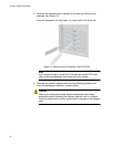
4. Connect the other end of the fiber optic cable to the appropriate
Ethernet network port or fiber optic port.
After connecting the system to the network and power is supplied, the
adapter performs auto-negotiation and attempts to establish the
connection at 1000 Mbps full-duplex only. The adapter port LED should be
functional at this point. See Table 1 on page 21 for a description of
adapter port LED operation.
Note
Even minor smudges or dirt on the end face of the fiber can disrupt
light transmission and lead to failure of the connection. For
instructions that describe how to clean the fiber optic connector, see
Appendix B “Cleaning Fiber Optic Connectors” on page 115
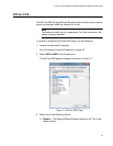
Twisted Pair
Copper Cable
If your AT-2911 series adapter is equipped with a twisted pair copper port,
you need a copper network cable with RJ-45 connectors. See “Twisted
Pair Copper Port” on page 20.
1. Connect one end of the cable to the adapter.
2. Connect the other end of the cable to the appropriate Ethernet network
port or twisted pair copper port.
After connecting the system to the network and power is supplied, the
adapter performs auto-negotiation and attempts to establish the
connection at the appropriate speed and duplex mode.
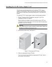
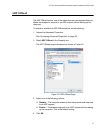
SFP Transceiver If your AT-2911 series adapter is equipped with an SFP slot, you must
have an SFP transceiver and an appropriate cable.
1. Insert an SFP transceiver into the SFP socket on the adapter until the
SFP transceiver snaps into place in the socket.
2. Remove a plug from the SFP transceiver.
3. Connect one end of the cable to the SFP transceiver.
4. Connect the other end of the cable to the appropriate Ethernet network
port or an appropriate port.
After connecting the system to the network and power is supplied, the
adapter performs auto-negotiation and attempts to establish the
connection at 1000 Mbps full-duplex only.