


AT-2973SX, AT-2973T, and AT-2973T/4 NetExtreme II Family Adapters Installation and User’s Guide
21
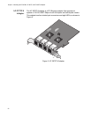
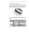
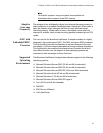
AT-2973T/4 Adapter Physical Description
The faceplate on the AT-2973T/4 adapter provides four twisted-pair
connectors for attaching the adapter to a compatible link partner. The ports
numbers are not shown on the card. See Figure 6 for the port numbers
and the LED assignments. When the adapter is mounted vertically, the top
LED is the Link LED and the bottom LED is the activity (ACT) LED.
Figure 6. AT-2973T/4 Faceplate
For copper-wire Ethernet connections, the state of the network link and
activity is indicated by the LEDs on the RJ-45 connector, as described in
Table 3.
Table 3. Network Link and Activity Indicated by the RJ-45 Port LEDs
Port LED LED Appearance Network State
Link LED Off No link (cable disconnected)
Continuously
illuminated
Link
Activity LED Off No network activity
Blinking Network activity
1862
T
LNK
ACT
ATI
LINK ACT
PORT 1
PORT 2
PORT 3
PORT 4