


AT-6102 Installation and User Guide 7
• Power Out port: It supports two types of power cable – Inner dimension 5.5 x 2.0mm, length
360 mm and 5.5 x 2.5 mm, length 360mm. Both cables are included in the POE Splitter
package. The Power Out port is capable of feeding 5V, 7.5V, 9V or 12V DC power to the
device.
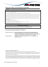
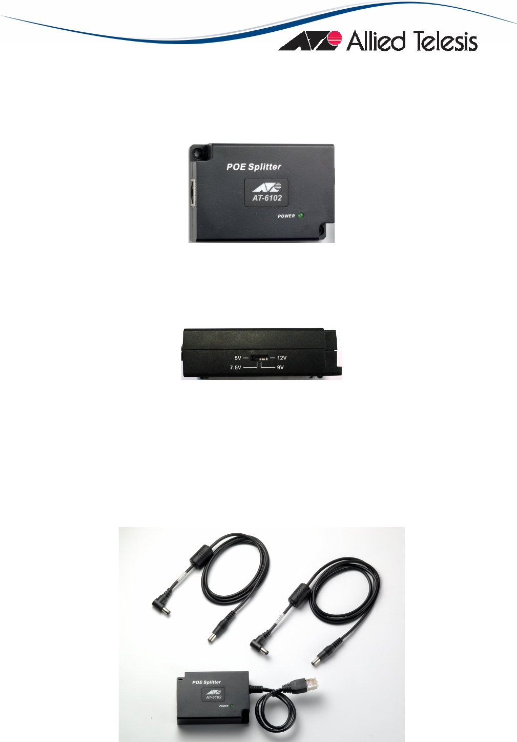
• LED indicator: one Power LED indicator for the system unit. It is located on the topside of the
Power over Ethernet Splitter
Figure 3: Power LED Indicator
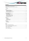
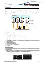
• Dipswitch: It allows the user to select the output DC voltage among four different values 5V,
7.5V, 9V and 12V. The POE Splitter comes factory set at 5V. Before changing the output
voltage level the POE Splitter must be switched off disconnecting the POE RJ-45 cable from
the Data In port.
Figure 4: DIP Switch
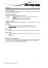
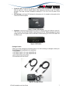
Package Content
Check your router package for the following items. If an item is missing or damaged, contact your
Allied Telesis sales representative for assistance.
1 x PoE Splitter
1 x DC Power Jack 5.5 x 2.0 mm, length 360 mm
1 x DC Power Jack 5.5 x 2.5 mm, length 360 mm
1 pair of self sticking Velcro Strips
This Installation and User Guide
Figure 5: Package content