


Installation and Safety Guide
25
Checking LEDs
The following LEDs report operations and faults on x900 Series and
SwitchBlade
x908 switches:
■ “System LEDs” on page 25
■ “Stacking LEDs” on page 27
■ “PWR01 LEDs” on page 27
■ “PWR02 LEDs” on page 27
■ “PWR05 AC LEDs” on page 28
LEDs for Ethernet ports and Small Form Factor Pluggable (SFP) ports are
described in the Hardware Reference.
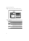
System
LEDs
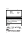
The following table describes how LEDs on the switch report operations and
faults.
LED State Description
PSU 1
and
PSU 2
Green The PSU is installed and supplying power to the
switch. The voltage output is within specification.
Red One of the following:
• The PSU is installed in the switch, and a fan has
failed or the PSU has exceeded its recommended
temperature threshold.
• A FOM is installed in the switch and a fan has
failed. The x900-12XT/S and SwitchBlade x908
switches do not support FOMs.
• The bay is empty. Applies to AT-8948, AT-9924Ts,
x900-24XT, x900-24XT-N, and x900-24XS
switches which require a FOM when only one
PSU is installed.
• Dual PSUs are installed, but the PSU is not
receiving power.
• The standby switch has been turned off.
Off A FOM is installed and operating at an acceptable
speed. For AT-9924T, x900-48FE, x900-48FE-N,
x900-48FS, and SwitchBlade
x908 switches, a blanking
plate is installed.