


Installation and Safety Guide
27
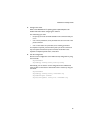
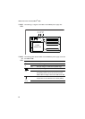
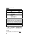
Stacking
LEDs
The following table describes how LEDs on the SwitchBlade x908 report
operations and faults on the rear panel stacking ports.
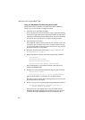
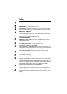
PWR01
LEDs
The following table describes LEDs on the PWR01 power supply unit.
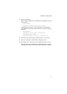
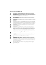
PWR02
LEDs
The following table describes LEDs on the PWR02 power supply unit.
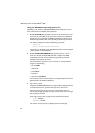
SD Green
flashing
The Secure Digital memory card is active and should
not be ejected. The card can be safely ejected when
the LED remains off. Valid for AT-9924Ts,
x900-12XT/S, x900-24XT, x900-24XT-N,
x900-24XS, and SwitchBlade
x908 switches.
LED State Description (cont)
LED State Description
STATUS Green The switch is the stack master.
Amber The switch is a stack member.
Green
flashing
The switch is in the process of learning the stack
topology and selecting the stack master.
Off The switch is not a stack member.
PORT 1
and
PORT 2
Green A link has been established.
Amber
flashing
The link has a transmission fault.
LED State Description
Fault Red The temperature on the PSU has exceeded the limit of
75º C (167º
F), or the fan failed.
PWR Green A PSU is installed in the switch and is delivering power.
A FOM does not have this LED.
LED State Description
Fault Red The temperature on the PSU has exceeded the limit of
75º C (167º
F), or the fan failed.
PWR Green A PSU is installed in the switch and is delivering power.
A FOM does not have this LED.