AT-FS750/16 and AT-FS750/24 Fast Ethernet Smart Switches Installation Guide
23
Collapsed
Backbone
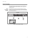
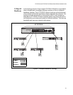
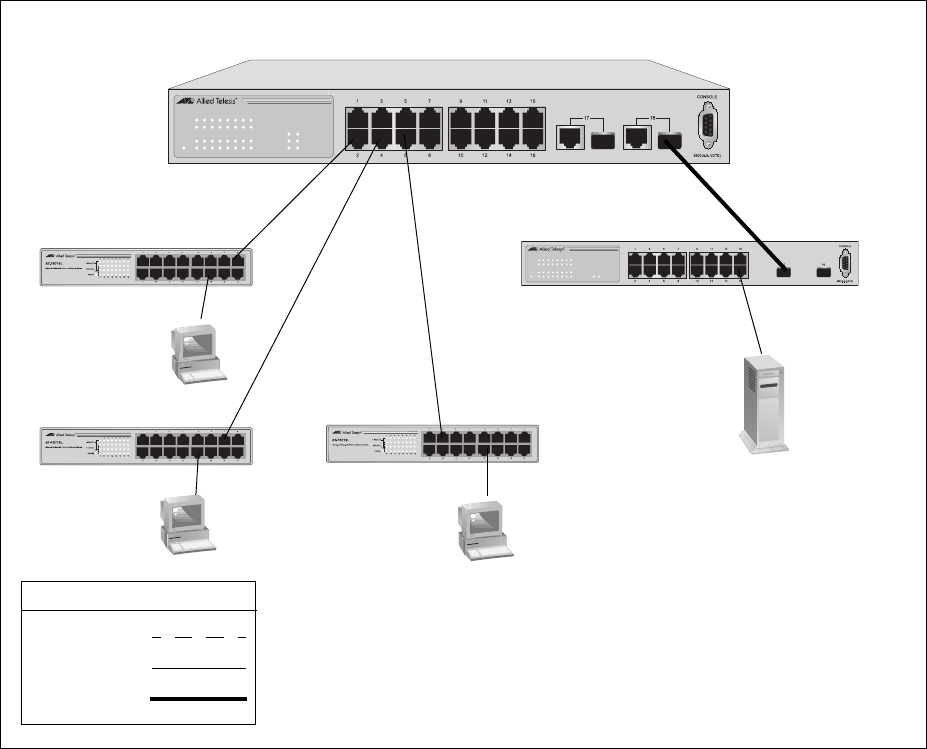
In the topology shown in Figure 5 the AT-FS750/16 Switch is connected to
other managed and unmanaged Ethernet switches to form a collapsed
backbone topology. The AT-FS750/16 Switch functions as the focal point
of the network by transferring Ethernet frames between the switches. This
topology reduces the amount of unnecessary traffic in each workgroup,
because the AT-FS750/16 Switch transfers frames only when the source
and destination end nodes are located on different switches. This frees up
bandwidth and improves network performance.
Figure 5. Collapsed Backbone Topology
1288
LINK/ACT
SPEED
LINK/ACT
SPEED
POWER
17 18
LINK/ACT
13579111315
2 4 6 8 10 12 14 16
1000M
100M
AT-FS750/16 16-Port 10/100Mbps + 2 SFP/1000T Combo WebSmart Switch
Legend
100 Mbps
1000 Mbps
10 Mbps
AT-FS750/16
LINK/ACT
SPEED
LINK/ACT
SPEED
POWER
1516
LINK/ACT
13579111315
2 46 810121416
AT-GS950/16 16-Port 10/100/1000Mbps + 2 SFP Combo WebSmart Switch


