


1 2 3
AT-CM3K0S Gigabit Ethernet
Media Converter Installation Guide
Overview
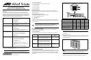
The AT-CM3K0S Media Converter is a member of the Converteon family of media
converter products. It is a simple and reliable way to connect Fast or Gigabit Ethernet
networks across small or large geographical distances with fiber optic cable. The product
features a 10/100/1000Base-T port for a local connection and a slot for a 100Base-FX or
1000Base-X SFP module for a remote connection using multimode or single-mode fiber
optic cable. The features of the media converter are listed here.
(* Requires the AT-CV5M02 Management Card.)
(** Requires the AT-CV5M02 Management Card in the upstream AT-CV5000 Chassis.)
Note
This line card cannot be managed with the AT-CV5M01 Management Card.
613-001062 Rev. A
Converteon Enclosures
This product is supported in all four Converteon enclosures:
AT-CV5000 Chassis
AT-CV1203 Chassis
AT-CV1200 Chassis
AT-CV1000 Chassis
Related Documents
For background information on the Converteon products, refer to the Converteon
AT-S73, AT-S99, and AT-S102 Management Software User’s Guide, available from the
Allied Telesis web site.
Verifying the Package Contents
The following items should be in the shipping container:
One AT-CM3K0S Media Converter
This Installation Guide
Warranty card
If any item is missing or damaged, contact your Allied Telesis sales representative for
assistance. You should retain the original shipping material in case you need to return the
unit to Allied Telesis.
Reviewing Safety Precautions
Before installing the media converter, review the safety precautions detailed in the
Converteon chassis’ Installation Guide.
Cable Specifications
The cable specifications for the 10/100/1000Base-T twisted pair port are listed here.
For the fiber optic cable specifications, refer to the SFP module instructions.
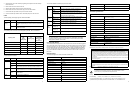
Setting the Operating Mode
There are DIP switches on the line card for setting the card’s operating mode. You can
also set the operating mode with the optional AT-CV5M02 Management Card. To use the
DIP switches, refer to the figure and table. For background information on the operating
modes, refer to the Converteon AT-S73, AT-S99, and AT-S102 Management Software
User’s Guide.
Installing the Media Converter
Note
The media converter supports hot swapping and can be installed while the chassis
is powered on.
To install the media converter:
1. Remove the slot cover from one of the slots in the Converteon chassis by loosening
the captive screw with a Phillips head screwdriver. The unit can be installed in any of
the media converter slots.
Note
Retain the slot cover and reinstall it if you ever remove the line card. An open slot
allows dust to enter the unit and reduces proper airflow in the chassis.
2. Align the edges of the line card with the guides in the slot and carefully slide the card
into the chassis until it is flush with the front of the chassis. Light pressure may be
needed to seat the module on the connector on the backplane in the chassis.
10/100/1000Base-T Twisted
Pair Port
IEEE 802.3u Auto-Negotiation
Half- or full-duplex mode
Auto-MDI/MDI-X
RJ-45 connector
IEEE 802.3x flow control at 10, 100, or 1000 Mbps
SFP Slot Supports 100Base-FX and 1000Base-X SFP modules (SFP
module sold separately.)
Operating Modes Link Test
MissingLink
™
Smart MissingLink
The operating modes can be activated with or without support
for Operations, Administration, and Maintenance.
Operations, Administration, and
Maintenance (OAM) Features
Loopback test*
Remote Converteon line card management*
Remote management software downloads*
Dying gasp**
Variable requests*
Other Features Jumbo frames up to 10,240 bytes
Ingress and egress packet rate limiting*
Operating mode and port status LEDs
Low power mode
Cyclical redundancy check
Suitable for managed and unmanaged network
environments
Management available with the AT-CV5M02 Management
Card
AT-S102 Management Software (preinstalled)
*613-001062 RevA*
Caution
The media converter line card is sensitive to and can be damaged by
electrostatic discharge. Wear a grounding device and observe electrostatic
discharge precautions when installing the card in the chassis.
Speed Cable Type
Maximum Operating
Distance
10 Mbps Standard TIA/EIA 568-B-compliant Category 3 or
better shielded or unshielded cabling with 100 ohm
impedance and a frequency of 16 MHz.
100 m (328 ft)
100 Mbps Standard TIA/EIA 568-A-compliant Category 5 or
TIA/EIA 568-B-compliant Enhanced Category 5
(Cat 5e) shielded or unshielded cabling with 100
ohm impedance and a frequency of 100 MHz.
100 m (328 ft)
1000 Mbps Standard TIA/EIA 568-A-compliant Category 5 or
TIA/EIA 568-B-compliant Enhanced Category 5
(Cat 5e) shielded or unshielded cabling with 100
ohm impedance and a frequency of 100 MHz.
100 m (328 ft)
Operating Mode Switch 4 Switch 3 Switch 2 Switch 1
Link Test (default setting) Off Off Off Off
MissingLink Off Off Off On
Smart MissingLink Off Off On Off
Link Test with OAM Off On Off Off
MissingLink with OAM Off On Off On
Smart MissingLink with OAM Off On On Off
ON
1
432
OFF
14
SW1
1446
ON
1
43
2
OFF
14
SW1
1447
DIP Switch 1
Off
On
DIP Switch 4
257