


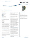

Link Test, MissingLink,
a
nd Smart MissingLink Functions
Link Test
The link test is a fast and easy way for you to test the
connections between the media converter ports and the
end-nodes that are connected to the ports. If a network
problem occurs, you can perform a link test to determine
which port is experiencing a problem, and so be able to
focus your troubleshooting efforts on the cable or end-node
where the problem resides.
M
issingLink
The MissingLink feature enables the two ports on the media
converter to pass the ‘Link’ status of their connections to each
other.When the media converter detects a loss of connection
to an end-node, the media converter shuts down the
connection to the other port, thus notifying the end-node that
the connection has been lost.
Smart MissingLink
The Smart MissingLink feature performs exactly the same
function as MissingLink with one additional feature. When a
link is lost on a port, the LINK LED of the port which still
has a valid connection to its end-node starts to blink. This
allo
ws you to quickly determine which port still has a valid
connection (LINK LED blinking) and which port has lost its
connection (LINK LED off).
Technical Specifications
Status Indicators
System LEDs
LED Color
Description
RDY Green The line card has passed diagnostics
Off The line card has not passed diagnostics
ML Green MissingLink mode is enabled
Off MissingLink mode is disabled
SML Green Smart MissingLink mode is enabled
Off Smart MissingLink mode is disabled
Fiber P
ort LEDs
LED Color Description
LK Green Link established on the port
Off No link established on the port
A
T
Green
TX/RX activity detected on the port
Off No activity detected on the port
Copper P
or
t LEDs
LED Color Description
LK Green Link established on the port
Off No link established on the port
AT Green TX/RX activity detected on the port
Off
No activity detected on the port
FD Green Port operating in full-duplex mode
Off Port operating in half-duplex mode
DIP Switches
The AT-CV102 line card features both the Diagnostic Mode
(Table 1) and Port Configuration (Table 2) DIP switches. The
tables below list the positions of the DIP switches.
Table 1. Diagnostic Mode DIP Switches Positions
‘X’ means the DIP switch position could be either On or Off.
Table 2 lists the Port Configuration DIP switches positions.
Table 2. Port Configuration DIP Switches Positions
‘X’ means the DIP switch position could be either On or Off.
Physical Specifications
Dimensions 2.2cm x 7.3cm x 13cm
(W x D x H) (0.855” x 2.89” x 5.1”)
Weight 0.27kg (0.60lbs)
Optical Characteristics
Connector type Dual SC or dual ST
Fiber type Single-mode or multi-mode
Operating distance 2km (1.24 miles) to 40km (24.8 miles)
Optical Output Power (dBm)
Product
Minimum Maximum Wavelength Connector
AT-CV101 -20dBm to -14dBm 1310nm Dual ST
A
T
-CV102
-20dBm to
-14dBm 1310nm Dual SC
A
T
-CV102/1 -15dBm to -5dBm 1310nm Dual SC
A
T-CV102/2 -15dBm to 0dBm 1310nm Dual SC
Receiv
er P
o
w
er Sensitivity (dBm)
Product
Minimum
Maximum
AT-CV101 -31dBm to -11dBm
AT-CV102 -31dBm to -11dBm
AT-CV102/1 -34dBm to -3dBm
AT-CV102/2 -34dBm to -3dBm
Power Characteristics
Power consumption 5.7W
CV10x SERIES | Converteon Series Line Card
USA Headquar
ters
|
19800 Nor
th Creek Parkway | Suite 200 | Bothell | WA 98011 | USA | T: +1 800 424 4284 | F: +1 425 481 3895
European Headquarters |Via Motta 24 | 6830 Chiasso | Switzerland | T: +41 91 69769.00 | F: +41 91 69769.11
Asia-Pacific Headquar
ters
|
11
T
ai Seng Link
|
Singa
pore | 534182 | T: +65 6383 3832 | F: +65 6383 3830
www.alliedtelesis.com
©
2007
Allied
T
elesis Inc
. All rights reserved.Information in this document is subject to change without notice. All company names,logos, and product designs that are trademarks or registered trademarks are the property of their respective owners. 617-000169 Rev E
O
perating Mode
D
IP 1
D
IP 2
D
IP 3
D
IP 4
Link Test (default) Off Off X X
Smart MissingLink
(SML)
Off On X X
MissingLink (ML) On Off X X
Manufacturing
Settings
Off Off Off Off
Operating Mode DIP 1 DIP 2 DIP 3 DIP 4
Auto MDI-X Enabled
(default)
X Off X X
Auto MDI-X Disabled X Off X X
Manufacturing
Settings
Off Off Off Off
Environmental Specifications
Maximum operating temperature: 0°C to 40°C
(32°F to 104°F)
Maximum storage temperature: -25°C to 70°C
(-13°F to 158°F)
Operating and storage altitude: Up to 3,048
meters
(10,000 feet)
Relative humidity operating and
storage (non-condensing): 5% to 95%
Predicted MTBF (Telcordia SR332):
AT-CV101 1,020,000 hrs
AT-CV102 890,000 hrs
AT-CV102/1 1,020,000 hrs
AT-CV102/2 1,020,000 hrs
Standards
EMI part 15:
FCC class A, EN55022 class A, VCCI class A, C-Tick, CE
Immunity:
EN55024
Safety:
UL60950-1 (cULUS), EN60950-1 (TUV)
EN60825
Ordering Information
AT-CV101
Fast Ethernet Converteon media converter line card,
100TX to 100FX, MMF, ST, 2km
AT-CV102
Fast Ethernet Converteon media converter line card,
100TX to 100FX, MMF, SC, 2km
AT-CV102/1
F
ast Ether
net Con
ver
teon media converter line card,
100TX to 100FX,
SMF, SC, 15km
A
T
-CV102/2
F
ast Ethernet Converteon media converter line card,
100TX to 100FX, SMF, SC, 40km