


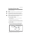

Removable Power Supply and Fan
14
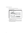
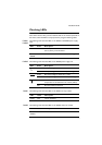
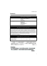
Switch The following table describes how LEDs on the switch report operations and
faults with installed PSUs and FOMs.
LED State Description
PSU 1
and
PSU 2
Green The PSU is installed and supplying power to the switch.
The voltage output is within specification.
Red One of the following:
• The PSU is installed in the switch, and a fan has
failed or the PSU has exceeded its recommended
temperature threshold of 70ºC (158º F).
• A FOM is installed in the switch and a fan has failed.
The x900-12XT/S and the SwitchBlade x908
switches do not support FOMs.
• The bay is empty. Applies to AT-8948, AT-9924Ts,
x900-24XT, x900-24XT-N, and x900-24XS
switches which require a FOM when only one PSU
is installed.
• Dual PSUs are installed, but the PSU is not
receiving power.
Off A FOM is installed and operating at an acceptable
speed. For AT-9924T, x900-48FE, x900-48FS, and
SwitchBlade x908 switches, a blanking plate is installed.