


Chapter 3: Installing the Switch and Modules
50
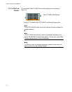
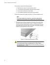
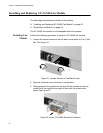
5. Tighten the captive screws to fasten of the power supply module to the
chassis. See Figure 20.
Figure 20. Tighten AT-PWR06 Captive Screws
6. The next step in the installation process is installing the fan modules.
Go to “Installing Fan Module” on page 52 for the installation
procedure.
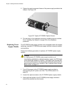
Replacing Power
Supply Module
The AT-PWR06 power supply module is hot swappable within the chassis
assuming a second AT-PWR06 power supply module is already installed
and operating.
Perform the following procedure to replace a AT-PWR06 power supply
module:
Caution
If a replacement AT-PWR06 power supply module is not
immediately available for a redundant power supply, t he PSU blank
cover should be installed in its place. This blank cover assures that
the correct airflow across the components within the chassis when a
power supply module is not installed. See “Installing Power Supply
Blank Cover” on page 51.
1. Turn off the power to the AT-PWR06 power supply module by
disconnecting the AC power cord. See “Turn Off the switch” on
page 68.
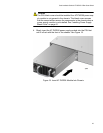
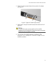
2. Loosen the captive screws on the AT-PWR06 power supply module.
3. Gently pull the handle of the AT-PWR06 power supply module to
remove the module from the chassis.