


Chapter 2: Installation
42
❒ Verify that you are using the appropriate type of fiber optic cabling.
❒ Verify that the operating specifications of the converter’s fiber optic
port are compatible with the fiber optic port on the remote end-
node.
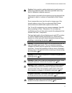
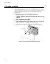
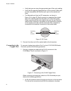
❒ The fiber optic port has two SC connectors, as shown in
Figure 10 on page 42. Each connects to a separate fiber strand.
One is for receiving data and the other is for transmitting data.
When connecting a fiber optic cable to the port, be sure that the
receiver fiber connector is connected to the transmitter connector
on the remote end-node, and the transmitter fiber connector is
connected to the receiver connector on the remote node.
Figure 10. SC Ports
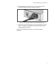
3. Connect the other end of the optical cable to the link partner.
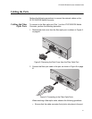
Connecting to the
Copper Port
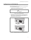
To connect a twisted pair cable to Port 2 on the AT-PC232/POE Media
Converter, perform the following procedure:
1. Connect a twisted pair cable with an RJ-45 connector to the
10/100Base-TX port, as shown in Figure 11.
Figure 11. Connecting to the RJ-45 Copper Ports
When connecting a twisted pair cable to an RJ-45 twisted pair port,
observe the following guidelines:
❒ An RJ-45 connector should fit snugly into the port on the converter.
The tab on the connector should lock the connector into place.
1TX RX
Transmitting
Receiving
Fiber
Connector
Fiber
Connector
1374