


Allied Telesis www.alliedtelesis.com
SWITCHBLADE
®
4000
| Layer 3 Modular Switch
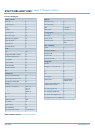
Card Wave Length Fibre Type Transmitter
dBm Min
Receiver
Sensitivity Max
dBm
(of same card)
dBm loss allowed
Max.
1
Minimum distance
using IEEE 802.3
fibre attenuation
(Km)
2 3
Received Power
Max. dBm avg.
4
AT-SB4352
32 port (MT-RJ)
1310nm 50.0um -20 -31 6 4.0 -14
AT-SB4352
32 port (MT-RJ)
1310nm 62.5um -23.5 -31 2.5 1.7 -14
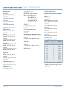
Power Outputs for Optical Ports
1
dBm loss allowed Max = Transmitter dBm min avg. - Receiver sensitivity max avg. - (2 x 1dBm per connector) - 3dBm buffer
2
Minimum distance using IEEE 802.3 fibre attenuation = dBm loss allowed max / Fibre cable attenuation (max)
3
Note, when calculating the actual distance the attenuation of the fibre optical cable, and all attenuators, must be used. Measurements may be required to determine this attenuation.
4
Max power received before transceiver stops receiving correctly.
5
Maximum distances calculated based on an allocation of 1.5dB total connections and splice loss for multi-mode fibre and 2.0dB for single-mode.
Description 62.5um MMF 50um MMF 10um SMF Unit
Nominal fibre specification wavelength (nM)
850 1300 850 1300 1310
Fibre cable attenuation (max) (dB/km)
1
3.75 1.5 3.5 1.5 0.5
Maximum fibre attenuation per km from IEEE 802.3 Table 38-12