


Installation and User’s Guides
This document contains an abbreviated version of the installation instructions for the AT-
TQ2450 Wireless Access Point. For complete installation and management instructions,
refer to the AT-TQ2450 installation Guide (613-001820) and AT-TQ2450 User’s Guide
(613-001821) on the Allied Telesis web site at www.alliedtelesis.com/support.
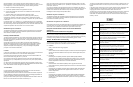
Safety and Electromagnetic Emissions Certificates
Installation Options
Table or desktop
Wall or ceiling with the optional AT-BRKT-J26 Bracket
Note:
The non-US model of this product has a country code setting that must be set during the
initial management session of the unit. The setting ensures that the unit operates in
compliance with the laws and regulations of your country or region.
For the US model the country code is preset and cannot be changed. Per FCC regulations,
the country code setting for all WiFi products marketed in the US must be fixed to US
operational channels only.
Physical Description
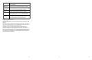
The front panel of the access point is shown in this figure.
The LEDs on the front panel of the access port are described in this table.
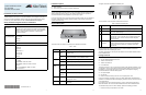
This figure shows the back panel of the access point.
The components on the back panel are described in this table.
You should review the safety precautions in the AT-TQ2450 Wireless Access Point
Installation Guide before installing the product.
The cable specifications for the LAN port are detailed in the AT-TQ2450 Wireless Access
Point Installation Guide.
Package Contents
The following items should be in the shipping container:
One AT-TQ2450 Wireless Access Point
Three 2.4 GHz antennas
Three 5 GHz antennas
Four rubber feet
The access point may or may not come with an AC/DC power adapter, depending on how
you ordered it. (You may have ordered it without the power adapter if you plan to use the
PoE feature.) If you did order the access point with the power adapter, the shipping
container should also contain the following items:
One power adapter
One tie wrap
Either one North American power cord or four regional power cords
If any item is missing or damaged, contact your Allied Telesis sales representative for
assistance. You should retain the original shipping material in case you need to return the
unit to Allied Telesis.
For instructions on how to install the device on a wall or ceiling with the optional AT-
BRKT-J26 Bracket, refer to the AT-TQ2450 Wireless Access Point Installation Guide.
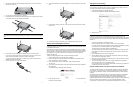
To install the access point on a table or desktop, perform the following procedure:
1. Place the access point upside down on a table.
Standard
Compliance
RoHs compliant
European Union RoHS (Directive 2011/65/EU of the European
Parliament and of the Council of 8 June 2011 on the restriction of
the use of certain hazardous substances in electrical and
electronic equipment.)
Electromagnetic
Compatibility (EMC)
EN55022/24
FCC Part15B
CISPR22
ICES-003
Medical (EMC) ETSI EN 60601-1-2:2007
Radio Equipment AS/NZS 4269
EN300328
EN391893
EN301489-1/-17
FCC Part 15C
FCC Part 15E
RSS-210
Safety UL UL60950-1 2nd edition
UL UL2043
CB IEC60950-1:2005+Am1:2009
LVD EN60950-1:2006+A11:2009+A1:2010+
A12:2011
TUV-T mark EN60950-1:2006+A11:2009+
A1:2010+A12:2011
Quick Installation Guide
AT-TQ2450
Wireless Access Point
*613-001831 Rev A*
613-001831 Rev. A
Table 1. LEDs
LED State Description
Power Solid
Green
The unit is receiving DC power that is within the normal
operating range.
Off The power supply is not receiving power from either the
AC/DC power adapter or a PoE Ethernet switch.
System Amber The access point is loading its firmware.
Off The unit is operating normally.
10M and
100M
10M: On
100M: Off
The Ethernet port is operating at 10 Mbps.
10M: Off
100M: On
The Ethernet port is operating at 100 Mbps.
10M: On
100M: On
The Ethernet port is operating at 1000 Mbps.
Radio1 Green The 2.4GHz radio and antennas are sending and
receiving radio waves.
Radio2 Green The 5GHz radio and antennas are sending and receiving
radio waves.
LEDs
2889
Table 2. Back Panel Components
Component Description
1 Console Port The Console Port is for manufacturing purposes only.
2 Rest Button The Reset button returns the parameter settings on the access
point to their default settings.
3 LAN Port The LAN port connects the access port to your wired network. It
supports PoE. If you connect the port to an Ethernet switch that
supports PoE, you do not have to use the AC/DC adapter to
power the device.
4 DC Power
Connector
The DC Power Connector connects to the AC/DC power adapter
included with the access point. You have to use the adapter if
you do not connect the LAN port to an Ethernet switch that
supports PoE.
CONSOLE PORT
RESET
5GHz
RESET
2.4GHz
LAN
10BASE-T/100BASE-TX/1000BASE-T
(AUTO MDI/MDI-X)
PoE IN
12VDC
2890
1 2 3 4
1 2 3