


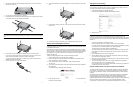
2. Affix the four rubber feet included with the access point to the four corners of the
bottom panel of the unit.
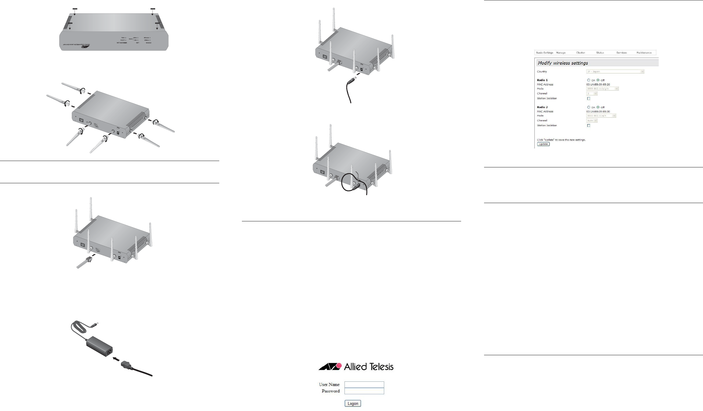
3. Turn the access point right side up on the table.
4. Install the three 2.4 GHz and three 5 GHz antennas to the corresponding connectors
on the sides of the unit. The connectors are labelled.
Note:
Do not attach the antennas when the access point is power on. Doing so may damage the
unit.
5. Attach a network cable to the LAN port.
6. Connect the other end of the network cable to a port on an Ethernet switch.
If you are not using the PoE feature on the Ethernet LAN Port to power the unit,
continue with this procedure to attach the AC/DC power adapter.
If you are using the PoE feature on the LAN Port to power the access point, the
installation procedure is complete.
7. Connect the power cord to the AC/DC adapter.
8. Connect the DC cable on the AC/DC adapter to the 12VDC connector on the access
point.
9. Secure the DC cable to the anchor on the unit with the tie wrap that comes with the
access point.
10. Connect the AC plug on the power cord to an appropriate AC power source.
Starting the Initial Management Session
This section contains an abbreviated version of the procedure for starting the initial
management session. For complete instructions, refer to the AT-TQ2450 installation Guide
or AT-TQ2450 User’s Guide.
The wireless access point has a DHCP client. The default setting for the client is enabled.
When you power on the access point for the first time, it queries the subnet on the LAN port
for a DHCP server. If a DHCP server responds to its query, the unit uses the IP address the
server assigns to it. If there is no DHCP server, the access point uses the default IP
address 192.168.1.230.
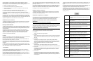
To start the initial management session, perform the following procedure:
1. Start the web browser on your management workstation.
2. Enter in the URL field of the web browser the IP address of the wireless access
point. The address is one of the following:
If your network does not have a DHCP server, enter the default address
192.168.1.230.
If your network has a DHCP server, enter the IP address the DHCP server assigned to
the access point.
The wireless access point displays the logon prompt.
3. Enter “manager” for the username and “friend” for the password. The username and
password are case-sensitive.
Setting the Country Setting
You should set the country setting during the initial management session to ensure that the
device operates in compliance with the codes and regulations of your region or country.
To set the country setting, perform the following procedure:
1. Select Wireless Settings from the Manage menu.
The access point displays the “Modify wireless settings” window.
2. Select the Country pull-down menu and select your country or region.
Note:
If the Country pull-down menu is deactivated and cannot be changed, the country
parameter was set when the unit was manufactured and cannot be changed. If the setting
is not correct for your country or region, contact your Allied Telesis sales representative for
assistance.
The access point displays a confirmation prompt.
3. Click OK to change the country setting or Cancel to cancel the procedure.
If you click OK, the access point changes the country setting and disables both radios
on the access point. (The default setting for the radios is disabled.)
This procedure does not require clicking the Update button.
You must now reboot the access point. The new country setting is not active until the
unit is rebooted. To reboot the unit, either power off and on the unit or continue with
these steps:
4. From the Maintenance menu, select Configuration.
5. Click the Reboot button in the To Reboot the Access Point section of the “Manage
the Access Point’s Configuration” window.
6. When the access point displays a confirmation prompt, click OK to reboot the unit or
Cancel to cancel the procedure.
7. To resume managing the unit, wait for it to complete initializing its management
software and then start a new management session.
For more instructions on how to configure the features of the access point, refer to the
AT-TQ2450 Access Point User’s Guide.
Federal Communication Commission Interference Statement
This device complies with Part 15 of the FCC Rules. Operation is subject to the following
two conditions: (1) This device may not cause harmful interference, and (2) this device
must accept any interference received, including interference that may cause undesired
operation.
This equipment has been tested and found to comply with the limits for a Class B digital
device, pursuant to Part 15 of the FCC Rules. These limits are designed to provide
reasonable protection against harmful interference in a residential installation. This
equipment generates, uses and can radiate radio frequency energy and, if not installed and
used in accordance with the instructions, may cause harmful interference to radio
communications. However, there is no guarantee that interference will not occur in a
2894
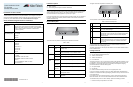
CONSOLE PORT
RESET
5GHz
RESET
2.4GHz
LAN
10BASE-T/100BASE-TX/1000BASE-T
(AUTO MDI/MDI-X)
PoE IN
12VDC
2.4GHz
5GHz
2895
CONSOLE PORT
RESET
5GHz
RESET
2.4GHz
LAN
10BASE-T/100BASE-TX/1000BASE-T
(AUTO MDI/MDI-X)
PoE IN
12VDC
2.4GHz
5GHz
2896
1577
CONSOLE PORT
RESET
5GHz
RESET
2.4GHz
LAN
10BASE-T/100BASE-TX/1000BASE-T
(AUTO MDI/MDI-X)
PoE IN
12VDC
2.4GHz
5GHz
2897
CONSOLE PORT
RESET
5GHz
RESET
2.4GHz
LAN
10BASE-T/100BASE-TX/1000BASE-T
(AUTO MDI/MDI-X)
PoE IN
2.4GHz
5GHz
12VDC
2898
4 5 6