


Chapter 1: Overview
22
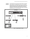
Network Topologies
This section illustrates two network topologies of the AT-FS750/16 and
AT-FS750/24 Fast Ethernet Smart Switches: a power workgroup and
collapsed backbone.
Power
Workgroup
Topology
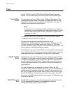
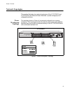
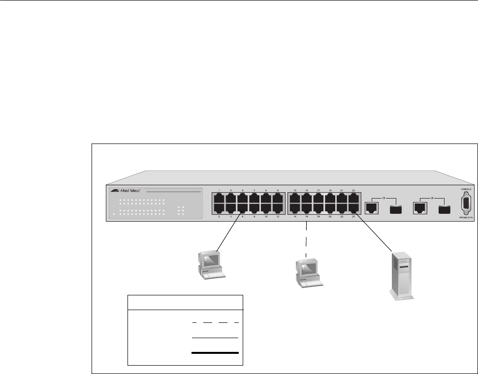
The topology shown in Figure 4 is commonly referred to as a power
workgroup. This topology provides the best in performance and reliability
because each end node is connected directly to the AT-FS750/24 Switch
with a dedicated network link.
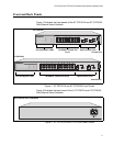
Figure 4. Power Workgroup Topology
AT-FS750/24
1290
1357911131517192123
POWER
2 4 6 8 10 12 14 16 18 20 22 24 25 26
LINK/ACT
LINK/ACT
SPEED
LINK/ACT
SPEED
AT-FS750/24
24-Port 10/100Mbps + 2 SFP/1000T Combo WebSmart Switch
1000M
100M
Legend
100 Mbps
1000 Mbps
10 Mbps