


Quick Install Guide 5
C613-04031-01 REV B
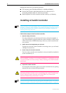
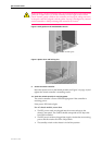
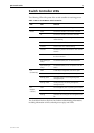
Figure 1: ESD socket on the SwitchBlade 8 chassis.
5. Install the CPU memory pack
Only Allied Telesyn supplied DIMMS have been tested and approved for use
with SwitchBlade switch controllers. Using DIMM that has not been approved
may cause unreliable operation and will invalidate the switch controller’s
warranty.
In an antistatic environment:
a) Lay the switch controller on a flat surface
b) Unpack the memory pack’s two DIMMs
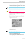
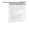
c) Holding a DIMM at an angle of about 30 degrees from horizontal, align
the notches on its connector strip with the notches on a DIMM slot (see
Figure 2 on page -5)
d) Insert the DIMM into the DIMM slot, sliding it along the two guides
until the retaining latches click into place. The latches should hold the
DIMM firmly in place
e) Repeat the process for the second DIMM
For the switch to function, both DIMMs must be installed (giving 256 MBytes of
DRAM per switch controller).
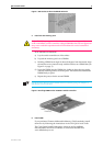
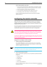
Figure 2: Installing DIMM on the AT-SB4211 Switch Controller.
6. Install CAM
If you purchased Content Addressable Memory (CAM) modules, install
them now by following the instructions in the CAM Quick Install Guide.
The CAM Quick Install Guide can be found on the SwitchBlade
Documentation and Tools CD-ROM, or can be downloaded from
www.alliedtelesyn.co.nz.
ESD socket
DIMM slot
DIMM