


6
Identifying External Components
This section identifies all the major external components of the switch.
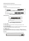
Front Panel
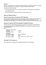
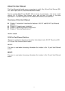
The figures below show the front panels of each of the switches.
Power
13 14 15 16
5
1
9
62
10
73
11
84
12
12345678910111213141516
LINK
100Mbps
16-port 10/100Mbps Fast Ethernet Switch
24-port 10/100Mbps Fast Ethernet Switch
LED Indicator Panel
16-port 10/100Mbps Fast Ethernet Switch
24-port 10/100Mbps Fast Ethernet Switch
Power (PWR)
This indicator lights green when the switch is receiving power, otherwise, it is off.
Link / Activity ( green )
This indicator lights green when the port is connected to a Fast Ethernet or Ethernet station,
if the indicator is blinking green then traffic is present on the port.
100Mbps ( green )
This LED indicator lights green when the port is connected to a 100Mbps Fast Ethernet
station. Otherwise, the LED is off when the port is connected to a 10Mbps Ethernet station.
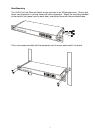
Rear Panel
The figure below shows the rear panel of the 16/24 Port Fast Ethernet switches.
AC Power Connector