


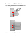


4. Pull the terminal block off the RNS5/8 and wire the power lines. Refer to the
Wiring the DC Power Inputs section for how to wire the power inputs.
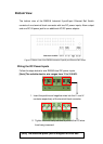
5. PWR1 and PWR2 dual power inputs can be connected to power sources
simultaneously. When the primary power source fails (the default setting is
PWR1), the system will automatically switch to the secondary power source
(PWR2), preventing any power interruption.
6. Check the LED for PWR1 and PWR2 to make sure that your RNS5/8 is
operating normally.
[Note] If you are using DC IN power jack to supply power to the
RNS5/8, please check the PWR LED
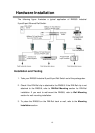
7. Use Category 5 straight through Ethernet cables with RJ45 connectors to
connect network devices.
8. Connect one side of an Ethernet cable with a RJ45 connector to the RNS5/8’s
Ethernet port (RJ-45 port), and the other side of the Ethernet cable to the
network device’s Ethernet port (RJ-45 port).
9. Check the port status LED indicator (blinking green) on the RNS5/8 to see if
the network connection is successfully established.
14