


Page 2 of 4
P/N 106547 REV D
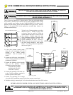
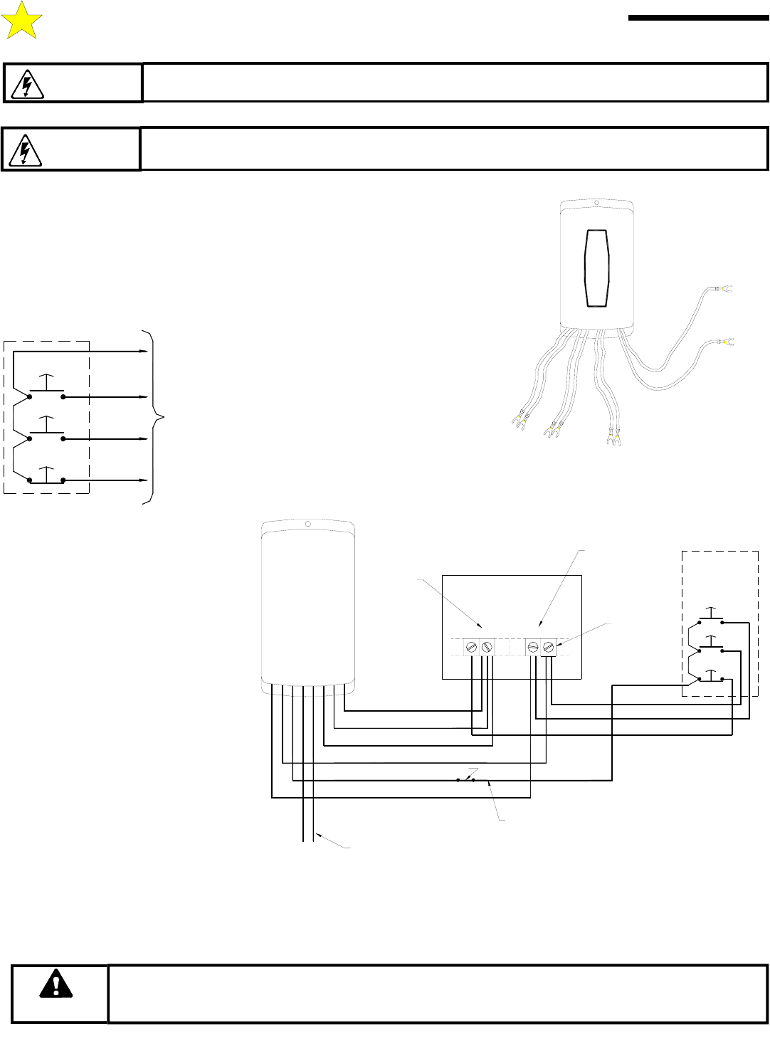
The 831E receiver functions as a 3-button station. Three sets of isolated contacts
are provided; normally open contacts for the OPEN PUSHBUTTON (orange
wires); normally open contacts for the CLOSE PUSHBUTTON (black wires);
normally closed contacts for the STOP PUSHBUTTON (gray wires). Refer to
Figure 1. For special STOP circuit applications, normally open contacts are
available from the factory.
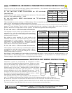
Typical 4-wire 3-button stations are wired as
shown in Figure 2. Number 18 gauge wire
or heavier must be used for wiring the
control stations and the 831E receiver to the
door operator. Smaller gauge wire may
cause operational problems, especially when
multiple 3-button stations are used. For
typical installations the 831E receiver is
mounted near the door operator, away from
any high voltage conduits or steel support
beams. For wiring, follow the steps below
and refer to Figure 3.
1. In the door operator control panel,
locate the wire connecting the door
operator to the 3-button station
COMMON. Note its location and
remove.
2. Connect one of the gray wires from the
831E to the wire just removed from the
pushbutton COMMON.
3. Connect the following wires from the
831E to the operator 3-button
COMMON (as shown at right):
ONE ORANGE (OPEN)
ONE BLACK (CLOSE)
ONE GRAY (STOP)
4. Connect the remaining 831E black wire
to the CLOSE pushbutton terminal in
the door operator control panel.
5. Connect the remaining 831E orange
wire to the OPEN pushbutton terminal in the door operator control panel.
6. Finish the wiring by connecting 24 VAC to the red and white wires of the 831E receiver.
BEFORE APPLYING POWER, CHECK ALL CONNECTIONS AND INSTALL THE ANTENNA.
IMPROPER WIRING COULD CAUSE ELECTROCUTION OR DAMAGE TO CIRCUITRY.
FOLLOW LOCAL BUILDING AND ELECTRICAL CODES.
WARNING
TO PREVENT ELECTROCUTION DISCONNECT POWER AT FUSE BOX AND DOOR OPENER
BEFORE WIRING PERMANENTLY.
WARNING
DO NOT USE RADIO CONTROLS ON COMMERCIAL DOOR OPERATORS UNLESS PROPER
ENTRAPMENT PROTECTION DEVICES ARE INSTALLED. CONSULT THE MANUFACTURER OF
YOUR OPERATOR FOR MORE DETAILS.
WARNING
831E COMMERCIAL RECEIVER WIRING INSTRUCTIONS
STOP
CLOSE
OPEN
TERMINAL STRIP
TO OPERATOR
WALL PUSHBUTTON STATION
Figure 2
105113
COMMERCIAL
STOP COM CLOSE
OPEN
OPERATOR
RECEIVER
MVP-831E
OPEN
STOP
CLOSE
WALL PUSH
BUTTON
ORANGE
BLACK
GRAY
BLACK
GRAY
ORANGE
WHITE
RED
COMMON
24 VAC
Removed Wire
(See Step 1)
Step 2
Step 3
Step 4
Step 5
Step 6
STATION
Figure 3
106549
R
E
D
W
H
I
T
E
G
R
A
Y
B
L
A
C
K
O
R
A
NG
E
24 VAC
STOP
CLOSE
OPEN
831E
RECEIVER