


4
The following items are included with the SPS-50:
1. 1- SPS-50 control box
2. 1- SPS-50 battery pack
3. 1- Relay output wire harness
4. 2- AC power in or power out wire harness
5. 1- Warning label
6. 1- Instruction Manual
INSTALLING THE SPS-50
The SPS-50 is not weather proof and must be protected from exposure. Ideally, the unit should be located inside the operator, away
from where water might infiltrate the operator. If there is no suitable space inside the operator, it may be located in an electrical
enclosure outside the operator. The battery pack must be connected to the SPS-50 control box with the leads provided. Do not route
low voltage wires in the same conduit as high voltage wires. Follow all local electrical codes or the national electrical code.
THE SPS-50 IS DESIGNED TO PROVIDE POWER
TO A GATE OPERATOR WHEN THE MAIN AC
POWER IS TURNED OFF. A GATE OPERATOR
CONNECTED TO THE SPS-50 MAY START
UNEXPECTEDLY WHEN THE MAIN AC POWER IS
TURNED OFF. WHEN SERVICING THE GATE
OPERATOR OF THE SPS-50 DISCONNECT THE
BATTERY PACK.
WARNING!
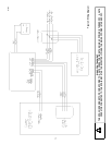
The SPS-50 consists of control box and a battery pack. Connectors are located on the SPS-50 control box for AC IN, AC OUT,
RELAY and BAT LO. Pre-wired harnesses are provided to mate with these connectors. The black and red wires are used to connect
to the battery pack. The LED’s indicate the status of the main AC voltage and the SPS-50 as follows:
AC ON: Green LED on, AC line voltage present
RELAY: Yellow LED on, relay NO output is closed to common, CM
INV ON: Yellow LED on, the SPS-50 is providing power to the gate operator
LO BAT: Red LED on, the LO BAT relay NO output is closed to common, CM
Refer to the figure below for the location of the connectors and LED’s.
W A R N I N G !
THE SPS-50 PRODUCES LETHAL VOLTAGES.
THE BATTERY PACK IS CAPABLE OF
SUPPLYING HAZARDOUS CURRENT. THE SPS-
50 SHOULD BE INSTALLED BY A QUALIFIED
TECHNICIAN.
WARNING!
DANGEROUS VOLTAGES MAY BE PRESENT
WHEN THE BATTERY PACK IS CONNECTED TO
THE SPS-50 CONTROL BOX. DO NOT CONNECT
THE BATTERY UNTIL INSTRUCTED TO DO SO.
DISCONNECT THE BATTERY PACK BEFORE
SERVICING.
Figure 1: Location of
Connectors and LED’s
107888