


22 021-511-B4-002, Rev. B
5.0 Operation
5.1 Start-up
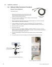
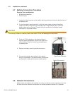
1. Verify the input voltage select switch on the power module is set for the correct input
voltage. The factory default setting is 240Vac.
2. Verify customer-end connections and apply AC power to the unit.
3. Connect the battery terminal left unplugged in Section 4.7.
5.2 Normal Operation
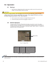
The green status LED will be ON solid after the battery connection is made. If any other
indication is present, see Section 6.0 for troubleshooting. Operating status of the MPS48-7M
is indicated by two status LEDs located on the power module. Refer to Table 5-1 to determine
operational status and possible faults.
Incorrect voltage selection can damage the unit and void the warranty. Verify the input
voltage select switch matches applied AC input power. Never apply 240Vac to a unit with
the input voltage select switch in the 120Vac position.
CAUTION!
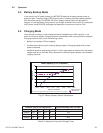
LED Color State Indication
Green Solid Output OK
Green Blinking Standby Operation
Red Blinking Battery Low/Missing
Red Solid Replace Battery
Red & Green Blinking Overload
Table 5-1, Status LED Indications
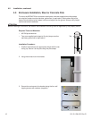
Fig. 5-1, Status LEDs
Status LEDs
NOTE:
When an Overload alarm and Battery Low/Missing alarm are present simultaneously, the Overload alarm will
take precedence.