


SWITCHERS
5
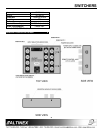
4.1 INPUT AND OUTPUTS
The DA1914SX uses four Female BNC
connectors for each input and output. The
DA1914SX can pass RGBS, RGsB, Component
Video, S-Video, and Composite Video signals.
Video signals must be passed through Red,
Green, and/or Blue channels; Sync channel is not
designed to pass video. C-Video must be passed
through the Green channel.
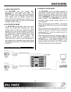
4.2 AUTO-SWITCH MODE
The DA1914SX automatically selects the active
source, by sensing the incoming sync. Sync
sensing occurs on the Sync channel for RGBS
signals and on the Green channel for RGsB or
Composite signals. The sync source switch should
be switched from SYNC to GREEN when using
RGsB or Composite Video sources. The
Composite source must be connected to the
Green channel in order for the auto-switcher to
work properly with composite video signals. When
both signals are present, the switcher will default
to INPUT 2.
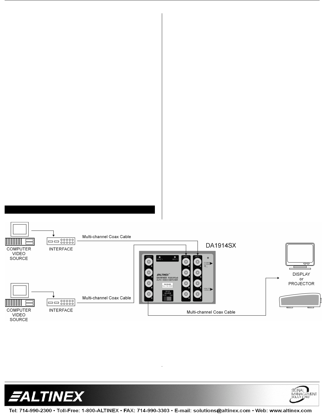
APPLICATION DIAGRAM 5
4.3 MANUAL SWITCH MODE
The DA1914SX can be controlled manually by
connecting a contact closure control switch to its
2.5mm mini-coaxial remote control jack. Altinex
offers a remote control switch with a 6 foot cable,
(Part # RC5203CC), which performs the manual
switch function. The DA1914SX can also be
controlled using contact closure relays on a
control system.
When an active source is on INPUT 1, the manual
switch will not affect the input, and will not switch
to INPUT 2.
When an active source is on INPUT 2, the manual
switch will act as an ON/OFF switch, forcing the
switcher to INPUT 1 when the contact closure is in
the CLOSED position.
When two active sources are present on INPUT 2
in the OPEN Switching Mode, the DA1914SX will
select INPUT 1. If the contact closure is in the
CLOSED position, and remains on INPUT 2, the
contact closure will switch to the OPEN position.
LED lights indicate the correct switching.