


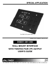

SPECIAL APPLICATION
400-0447-003
9
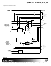
INSTALLING YOUR DS801-201/202 6
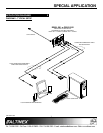
Step 1. Determine the best location for the
DS801-201/202 and TP Receiver. Where
possible, locate the DS801-201/202 as
close to the video source as possible and
the receiver as close to the receiving
component as feasible.
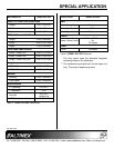
Step 2. Apply power to the 2-pin terminal block on
the rear of the DS801-201/202.
NOTE: The power supply should provide
9 VDC and be capable of
supplying 500 mA.
Step 3. The Power LED should be on and red.
Step 4. Connect the video and audio sources to
the input of the DS801-201/202 using
high quality cables.
Step 5. The Power LED should change from red
to green indicating a signal is present.
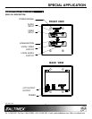
Step 6. Connect a local monitor and speakers to
the local outputs on the DS801-201/202.
These connections are not required for
proper operation of the transmitter, but
are provided for convenience.
Step 7. Run a UTP-type (CAT-5/CAT-5e) cable
from the 4TP OUTPUT on the rear of the
DS801-201/202 Transmitter to the 4TP
INPUT on the TP Receiver.
NOTE: Ensure good signal transmission
by routing the cable so as to
avoid any sharp angles, creases,
or bends.
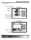
Step 8. Connect the TP Receiver per its
installation instructions. In the case of the
DS801-111, when the TP signal from the
DS801-201/202 is applied, the Power
LED will turn from red to green.
Step 9. Connect the receiver video and audio
outputs to their respective display and
amplifying devices.
Step 10. The units are now operational.
OPERATION 7
The DS801-201/202 requires no adjustments for
normal operation. Once connected and the
equalization set, the DS801-201/202 will work
trouble-free with no user intervention. Depending
on the TP receiver, cable lengths between units
should be 400 ft (122 m) or less.
TROUBLESHOOTING GUIDE 8
We have carefully tested and have found no
problems in the supplied DS801-201/202.
However, we would like to offer suggestions for the
following:
8.1 NO DISPLAY
Cause 1: The source has a problem.
Solution: Check the source and make sure
there is a signal present and all
source connections are correct. If
the source is working and there is
still no display, see Cause 2.
Cause 2: The path has a problem.
Solution: Connect the transmitter directly to
the receiver using a short UTP
patch cable. If the image is good,
there is a problem with the cable.
Otherwise, see Cause 3.
Cause 3: Cable connections are incorrect.
Solution: Make sure that cables are properly
connected. Also, make sure that the
continuity and wiring are good. If
there is still no display present, see
Cause 4.
Cause 4: Video equalization required.
Solution: Adjust the VIDEO EQUALIZATION
on the transmitter. Long cable runs
may require adjustments to near
maximum.
In general, cable runs less than 50 ft
(15 m) require little or no video
equalization and should be set to
minimum. Cable runs up to 400 ft
(122 m) will require near maximum
equalization on the receiver.