


SWITCHER
400-0426-006
7
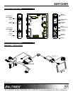
INSTALLING YOUR SW104-130 6
Step 1. Make sure to use the ALTINEX power
adapter supplied with the unit. Connect
the power adapter to the power port. The
Power and Input 2 LEDs should turn on.
NOTE: Input 2 is the default if there is no
signal on Input 1 and the Control
Switch is in the Auto position.
Step 2. Connect a video and audio source to
Input 1. If there is a properly formatted
input signal on Input 1, the switcher will
switch to Input 1 automatically, and the
Input 1 LED will turn on.
Step 3. Connect a video and audio source to
Input 2. If there is a properly formatted
input signal on Input 1, the switcher will
remain on Input 1.
Step 4. Connect the local video and audio outputs
to the local monitor and speakers.
Step 5. If a remote switch is to be used, connect
the control cable to the Input Select port.
See Section 7 for operation control.
Step 6. Verify that the picture quality on the
display is good. If a signal is not being
received, make sure that the display is
compatible with the resolution of the
computer graphics card.
Step 7. Connect the 4TP Main Output to the input
of the Twisted Pair receiver.
NOTE: Connect the Twisted Pair
receiver per its instructions.
Step 8. The SW104-130 is now ready for
operation. Depending on the length of the
cable, the video equalization adjustment
may need to be adjusted for optimal
performance.
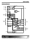
OPERATION 7
The SW104-130 requires only one adjustment to be
made for optimal performance. The adjustment is
video equalization for long cable lengths. The
remaining controls are for input selection only.
7.1 VIDEO EQUALIZATION
Video equalization is provided to fine-tune the
displayed image on the remote display. The
equalization adjustments on the SW104-130
and Twisted Pair receiver work together.
Start by setting both units to minimum and then
increase slowly. Some monitors respond very
quickly to changes in the equalization, others
may not display an image until the equalization
is set precisely.
7.2 SWITCH MODES
7.1.1 AUTO-SWITCH MODE
In auto-switch mode, the SW104-130 automatically
selects Input 2 if no active signal is present on
Input 1. If a signal is on Input 2 and not on Input 1,
the SW104-130 will maintain Input 2. However,
when an active signal is applied to Input 1, the
SW104-130 will switch to Input 1. If active signals
are on both inputs, the SW104-130 will
automatically switch to Input 1.
7.1.2 MANUAL-SWITCH MODE
The SW104-130 control switch allows switching
between Input 1 and Input 2. Placing the control
switch in either the Input 1 or Input 2 position forces
the source signal to the main and local outputs
thereby disabling auto-switching.
7.1.3 REMOTE SWITCH MODE
Remote switching is achieved via a contact closure
on the Input Select jack. Remote switching mode
disables both auto-switching and the Control Switch
position. A closed contact selects Input 1 and an
open contact selects Input 2.