


TABLETOP SOLUTIONS
400-0434-003 8
INSTALLATION PROCEDURES 7
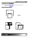
Step 1. Cut an opening into the table’s surface.
Refer to the ALTINEX website at
www.altinex.com for table cutout
requirements.
Note: The table can be 2.25” or less in
thickness. Always confirm dimensions
before cutting to insure that specifications
have not changed.
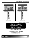
Step 2. Insert the Tilt ‘N Plug Jr. into the table
cutout.
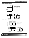
Step 3. Place the support brackets under the
table and place them between the support
mount grooves on the side of the
Tilt ‘N Plug Jr. Attach the brackets to the
groove at the desired height and secure
them to the bottom of the table using the
thumb-screws provided.
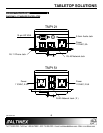
Step 4. Secure the cables by using the provided
cable clamps and screws included with
the unit. Pass the power cord from the
bottom of the housing and attach it to the
table using the cable clamp and screw
supplied with the Tilt ‘N Plug Jr.
Leave enough slack in the service loop to
allow for easy opening and closing, but
not too much as to cause excess
drooping of the service loop.
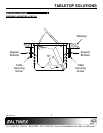
Step 5. Connect the appropriate cables with the
correct input connectors on the bottom of
the unit.
Step 6. Once you have applied power and
connected the proper cables on the
bottom of the unit you may raise the unit.
To raise the Tilt ‘N Plug Jr. into position,
push down on the front of the top cover;
the latching mechanism will then release,
allowing the pneumatic spring to raise it
into position.
Step 7. To lower the unit, push on the top of the
Tilt ‘N Plug Jr. until it locks into place.
TROUBLESHOOTING GUIDE 8
The Tilt ‘N Plug Jr. supplied was carefully tested
and no problems were detected. However, we
would like to offer the following suggestions:
• Please make sure that the highest quality
network cables are used.
• Make sure that no cable or power cord is
damaged or pinched. If there has been damage,
do not use the Tilt ‘N Plug Jr. Please call the
ALTINEX Customer Service Department at
(714) 990-2300 to have the unit repaired.
• If the unit does not rise into position correctly,
check the service loops for the signal and power
cords on the bottom of the unit.
ALTINEX POLICIES 9
9.1 LIMITED WARRANTY/RETURN POLICIES
Please see the ALTINEX website at
www.altinex.com for details on warranty and
return policies.
9.2 CONTACT INFORMATION
ALTINEX, Inc.
592 Apollo Street
Brea, CA 92821 USA
TEL: 714 990-2300
TOLL FREE: 1-800-ALTINEX
WEB: www.altinex.com
E-MAIL: solutions@altinex.com