


7
Chapter 3
Connectors, Headers & Jumpers Setting
3-1 Connectors
(1)
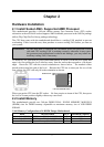
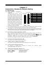
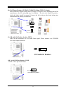
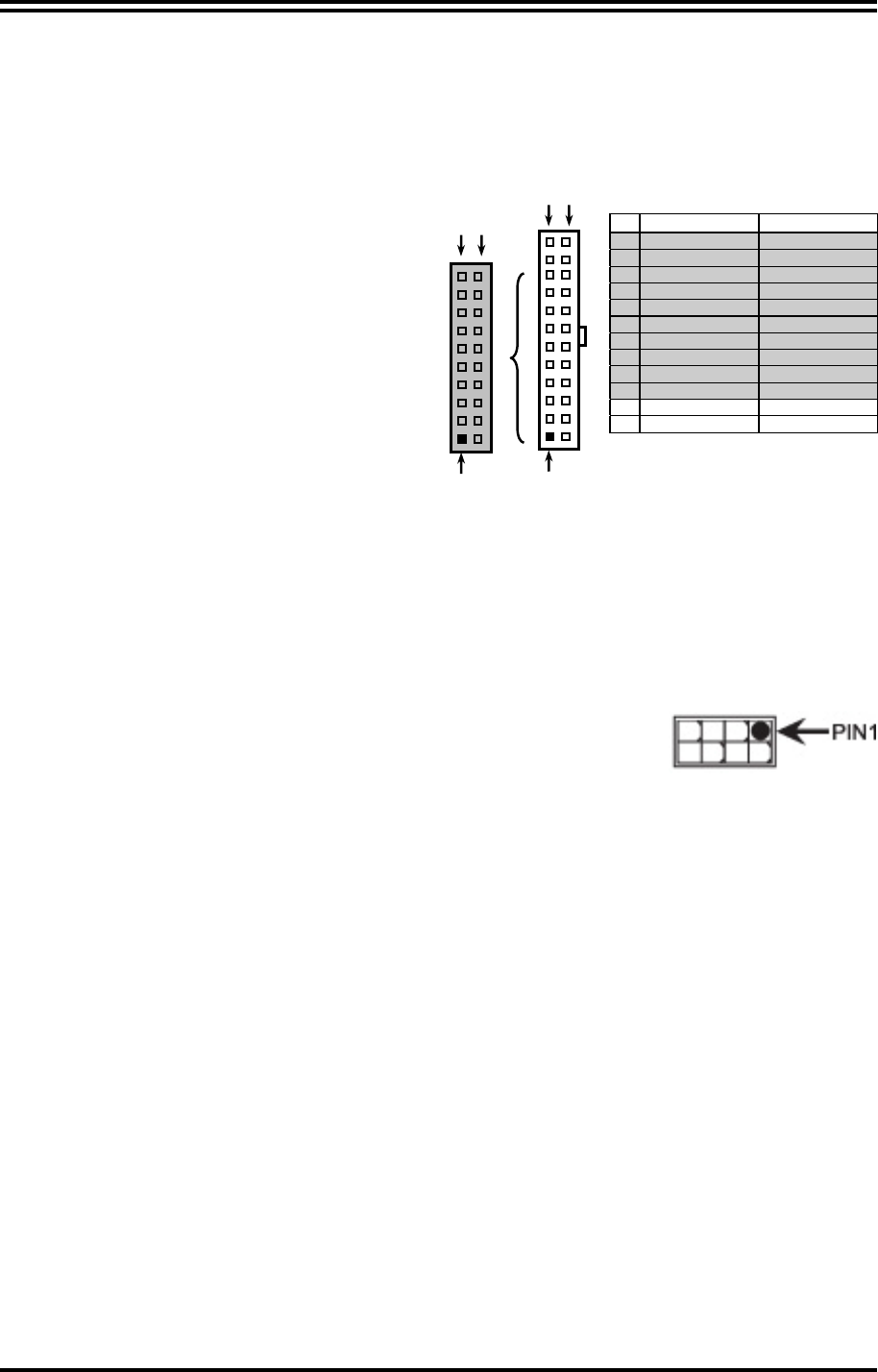
Power Connector (24-pinblock) :
ATXPWR1
ATX Power Supply connector: This is a
new defined 24-pins connector that
usually comes with ATX case. The ATX
Power Supply allows using soft power on
momentary switch that connect from the
front panel switch to 2-pins Power On
jumper pole on the motherboard. When
the power switch on the back of the ATX
power supply turned on, the full power
will not come into the system board until
the front panel switch is momentarily
pressed. Press this switch again will turn
off the power to the system board.
** We recommend that you use an ATX 12V Specification 2.0-compliant power supply unit (PSU)
with a minimum of 350W power rating. This type has 24-pin and 4-pin power plugs.
** If you intend to use a PSU with 20-pin and 4-pin power plugs, make sure that the 20-pin power plug
can provide at least 15A on +12V and the power supply unit has a minimum power rating of 350W.
The system may become unstable or may not boot up if the power is inadequate.
(2)
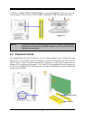
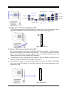
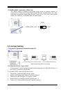
ATX 12V Power Connector (8-pin block) : ATX12V
This is a new defined 8-pins connector that usually comes with ATX Power Supply. The ATX Power
Supply which fully supports AM2 processor must including this
connector for support extra 12V voltage to maintain system power
consumption. Without this connector might cause system unstable
because the power supply can not provide sufficient current for system.
(3) PS/2 Mouse & PS/2 Keyboard Connector: KB
The connectors are for PS/2 keyboard and PS/2 Mouse
.
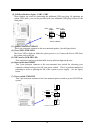
(4) USB Port connector: USB Port from CN5&UL1
The connectors are 4-pin connectors that connect USB devices to the system board.
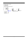
(5) LAN Port connector: RJ-45 port from UL1
This connector is standard RJ-45 connector for Network, The USBLAN1 support
10M/100Mb/1000Mb s data transfer rate
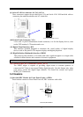
(6) Audio Line-In, Lin-Out, MIC Connector: CN3
This Connector is 3 phone Jack for LINE-OUT, LINE-IN, MIC
Line-in : (BLUE) Audio input to sound chip
Line-out : (GREEN) Audio output to speaker
MIC : (PINK) Microphone Connector
Pin 1
ROW1 ROW2
24-Pin
ROW1 ROW2
Pin 1
20-Pin
PIN ROW1 ROW2
1 3.3V 3.3V
2 3.3V -12V
3 GND GND
4 5V Soft Power On
5 GND GND
6 5V GND
7 GND GND
8 Power OK -5V
9 +5V (for Soft Logic) +5V
10 +12V +5V
11 +12V +5V
12 +3V GND