


LE-366 User’s Manual
-3-
Index
Chapter 1 <Introduction>
....................................................................6
1.1 <Product Overview> ...............................................................................6
1.2 <Product Specification>.........................................................................7
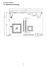
1.3 <Mechanical Drawing> ...........................................................................9
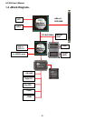
1.4 <Block Diagram>...................................................................................10
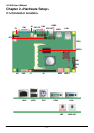
2.1<Connector Location>...........................................................................11
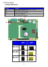
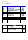
2.1.1 <Connector Reference> ............................................................. 13
2.1.2 <External Connector>................................................................. 13
2.2 <CPU and Memory Setup> ...................................................................14
2.2.1 <CPU Setup> .............................................................................14
2.2.2 <Memory Setup>........................................................................14
2.3 <Enhanced IDE & CF Interface> ..........................................................16
2.4 <Floppy Port> ........................................................................................17
2.4.1 <Analog VGA Interface> ............................................................18
2.4.2 <Digital Display>.........................................................................19
2.5 <GPIO Interface>...................................................................................24
2.6 <Serial Port Jumper Setting >..............................................................25
2.6.1 <Power Input> ............................................................................26
2.6.2 <Power Output> .........................................................................26
Chapter 3 <BIOS Setup>....................................................................30
Appendix A <I/O Port Pin Assignment>.................................32
A.1 <IDE Port> .............................................................................................32
A.2 <Floppy Port>........................................................................................33
A.3 <Serial Port>..........................................................................................33
A.4 <CRT Port>............................................................................................34
A.5 <LAN Port>............................................................................................34
A.6 < USB Port >..........................................................................................34