


LE-366 User’s Manual
-28-
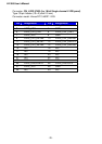
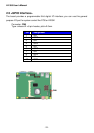
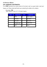
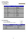
2.8 <Indicator and Switch>
The JFRNT provides front control panel of the board, such as power button, reset and
beeper, etc. Please check well before you connecting the cables on the chassis.
Connector: CN3
Type: onboard 14-pin (2 x 7) 2.54-pitch header
Pin Assignment Pin Assignment
1 GND 2
Power Switch
3 BUZZER- 4
BUZZER+
5 HD_LED- 6
HD_LED+
7 POWER LED- 8
Power LED+
9 GND 10
Reset