


NX800LX
2
Contents
Safety Information ..........................................................................................................4
Technical Support ............................................................................................................5
Conventions Used in This Guide ....................................................................................5
Packing List.......................................................................................................................6
Revision History ...............................................................................................................7
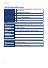
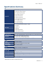
Specifications Summary..................................................................................................8
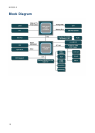
Block Diagram.................................................................................................................10
Production Introduction ...............................................................................................12
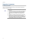
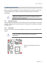
1.1 Before you Proceed ................................................................................................12
1.2 Motherboard Overview............................................................................................13
1.2.1 Placement Direction ....................................................................................................................... 13
1.2.2 Screw Holes ................................................................................................................................... 13
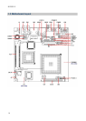
1.3 Motherboard Layout ................................................................................................14
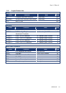
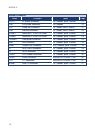
1.3.1 Layout Content List ........................................................................................................................ 15
1.4 Expansion Slots ......................................................................................................17
1.4.1 Installing an Expansion Card ......................................................................................................... 17
1.4.2 Configuring an Expansion Card ..................................................................................................... 17
1.5 Jumpers ..................................................................................................................18
1.5.1 Clear CMOS (J3)............................................................................................................................ 18
1.5.2 LCD Backlight Brightness Adjustment Connector (LCDPJ1)......................................................... 19
1.5.3 COM1/COM2 RI/+5V Selection (COMAJ1, COMBJ1)................................................................... 19
1.5.4 COM1/COM2 +5V/+12V Selection (COMAPJ1, COMBPJ1) ......................................................... 19
1.6 Connectors..............................................................................................................20
1.6.1 Rear Panel Connectors.................................................................................................................. 20
1.6.2 CF Power Connector (CFPJ1) ....................................................................................................... 21
1.6.3 ATX Power Connector (CN5)......................................................................................................... 21
1.6.4 Power Fan Connector (CN7).......................................................................................................... 21
1.6.5 SM Bus Connector (CN8) .............................................................................................................. 22
1.6.6 Serial port 1 in RS-232 mode (COMB1)......................................................................................... 22
1.6.7 Serial port 2 in RS-232 mode (COMB2)......................................................................................... 22
1.6.8 Front Panel Connector (FPANEL1)................................................................................................ 23
1.6.9 IrDA Connector (IRB1) ................................................................................................................... 24
1.6.10 Primary IDE Connector (IDEB1) ................................................................................................ 24
1.6.11 AC97 Line-in Connector (J1) .....................................................................................................25
1.6.12 GPIO Connector (J2) ................................................................................................................. 25