


APC Supplemental Equipment Protection Policy
(Valid only in the USA and Canada)
1. THIS SUPPLEMENTAL POLICY IS NOT A WARRANTY. REFER TO THE APC LIMITED WARRANTY STATEMENT FOR INFORMATION
CONCERNING THE WARRANTY FOR THIS PRODUCT.
2. THE SUPPLEMENTAL EQUIPMENT PROTECTION POLICY (SEPP) IS VALID ONLY WHEN CONNECTED SYSTEM EQUIPMENT IS
PROTECTED BY: A) BOTH THE APC DATA LINE PROTECTOR PRODUCT AND APC POWER (UTILITY LINE) PROTECTION EQUIP-
MENT (e.g. uninterruptible power source or surge suppressor); OR, B) APC POWER PROTECTION EQUIPMENT WITH BUILT-IN DATA LINE
PROTECTION. A special exception is made for electronic equipment properly connected to the ProtectNet model PTEL1-4, whose sole means of
power is via the telephone line. In such case, the telephone service equipment must include a properly installed and operating “primary protection”
device at the service entrance (such devices are normally added during premise telephone line installation) to be covered under this Policy. Call APC
Technical Support (800) 800-4APC for a copy of the complete Equipment Protection Policy.
3. This SEPP is valid only when all data lines to and from the connected system equipment are protected by an APC protection product.
4. Refer to the Equipment Protection Policy (EPP) provided with the APC power protection product for general Policy descriptions and informa-
tion on limitations, eligibility, and coverage qualifications. This Supplemental Equipment Policy supersedes the Equipment Protection Policy only as
follows:
A. Damage to electronic equipment resting from transients on data lines is covered with the exception of the following listed circumstances. Note
that all other exceptions, conditions, and limitations of the EPP are maintained.
1. Damage caused by failure to provide a suitable environment for the product, including, but not limited to, lack of a proper safety ground.
2. Damage caused by the use of the APC product for purposes other than those for which it was designed.
3. Damage to Ethernet or Token Ring Network Interface Cards, Hubs, and other LAN connected equipment that do not meet the applicable isola-
tion requirements of ANSI/IEEE Standard 802.3 (also ISO/IEC 8802-3) or ANSI/IEEE Standard 802.5.
B. Reimbursement (cost or repair or fair market value) Dollar Limits, as stated in the EPP, are doubled in value for customers that meet the qualifica-
tions and conditions set forth in both the SEPP and EPP.
5. Refer to the EPP for detailed information on submitting an Equipment Protection Policy Claim. Call the APC Customer Service Department at
(800) 800-4APC if you require additional information.
Limited Warranty
American Power Conversion offers a limited Lifetime Warranty on ProtectNet surge suppressors. APC warrants its products to be free from defects
in materials and workmanship under normal use and service for the lifetime of the original purchaser. Its obligation under this warranty is limited to
repairing or replacing, at its sole option, any such defective products. To obtain service under warranty you must obtain a Returned Material Autho-
rization (RMA) number from APC or an APC Service Center with transportation charges prepaid. The returned merchandise must be accompanied
by a brief description of the problem and proof of date of purchase. This warranty applies only to the original purchaser.
n Many APC UPSs provide a “TVSS Ground” screw for fasten-
ing the ground terminal. Use this screw wherever pos-
sible. Again, verify that the UPS is plugged into a three-wire
grounded outlet.
n Fasten the ground wire to the network system ground, if
possible, or beneath the head of a metal screw on the chas-
sis of the protected equipment. Do not loosen chassis screws
that secure internal components.
n Fasten the ground terminal beneath the head of a wall out-
let cover plate (120V systems only). Where possible, this
should be the same outlet where your protected equipment
is plugged in.
CAUTION: Disconnect power to the outlet by removing the branch
fuse or switching off the circuit breaker before attempting to loosen
the cover plate screw. Do not overtighten the screw.
n Fasten the ground terminal beneath a clamp secured around
a cold water pipe.
4.0 Specifications
Lines protected: All eight conductors.
Mode of protection: between send/receive pairs and any signal
line to ground.
Peak voltage: ± 6,000 Volts, 1.2/50 µs test waveform. (IEEE587)
Peak current: 250 Amps, 8/20 µs test waveform. (IEEE587)
Breakover: (turn on) voltage: 19V nominal between send/re-
ceive pairs.
Agency approvals: UL 497B listed
Isolated Loop Circuit Protector
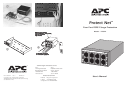
1.0 Introduction
Thank you for purchasing this American Power Conversion surge
protector, model P232-4. It is for use with RS232 communication
equipment (RS232 multiports, async multiplexers, async printer
spoolers) comprised of unshielded, twisted-pair wiring with RJ-
45 connectors. It protects up to four ports per unit. Use as many
P232-4s as needed to protect your network. P232-4 comes with 4
network jumper cables, stack or wall mount brackets and screws,
and grounding cables. See figure 1. Up to 10 P232-4s can be rack
mounted using the APC rack mounting kit, part number PRM,
available from your dealer or from APC at 1-800-800-4APC. See
figure 2 for optional rack mount configuration.
Please fill out and return the enclosed warranty registration card.
2.0 Safety
Please read and save these instructions, and take the following
safety precautions.
n Use the P232-4 in a protected environment only.
n To fully protect the user and equipment, the product must
be connected to a proper ground as described in 3.0 below.
3.0 Installation
1. Refer to figure 4. To install the ProtectNet with existing LAN
equipment, skip to paragraph 2 below. For new installations,
complete installation of all new RS232 equipment per the
manufacturer’s instructions without the ProtectNet and verify
that the new equipment operates properly.
2. Switch off the equipment to be protected and unplug the
serial cables.
3. Plug the UTP cables from the RS232 ports into the P232-4
“IN” jacks as shown.
4. Attach the supplied patch cables between the P232-4 “OUT”
jacks and the equipment UTP port jacks.
5. Connect the ProtectNet ground wire terminals to a proper
ground (protective earth) as described in the section on ground-
ing below .
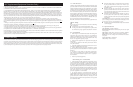
6. The P232-4 can be placed on a flat surface, mounted on a
wall, stacked, or mounted on the optional rack shelf. Figure 2
shows a rack mount installation. Figure 4 shows a typical sur-
face installation.
7. Switch on protected equipment.
Grounding the ProtectNet
1. Verify that the protected equipment is plugged into a three-
wire grounded outlet, if applicable. If your site has outlets with
only two holes (no center ground), a qualified electrician should
be called to upgrade your building wiring. Many APC UPS and
surge suppression products have a Site Wiring Fault Indicator
that warns of improper building wiring, including lack of a safety
ground. An outlet wiring tester can be purchased at most hard-
ware stores, though it is not as sensitive. Use of APC power
protection equipment is recommended.
2. For ganged, stacked, or rack mounted units, connect the
supplied short grounding wire from P232-4 to P232-4 daisy chain
fashion. Then use the supplied long ground wire to make the
ground connection. Ground the P232-4 by choosing one of the
following measures, listed in order of preference. Do not ground
to the rack mount shelf.