


Chapter 3 Hardware
20 Reference Manual CoreModule 420
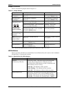
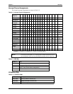
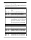
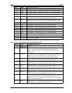
Interrupt Channel Assignments
The channel interrupt assignments are shown in Table 3-2.
Table 3-2. Interrupt Channel Assignments
Device vs
IRQ No.
0 1 2 3 4 5 6 7 8 9 10 11 12 13 14 15 Disable
Timer X
Keyboard X
Secondary
Cascade
X
COM1 D Z
COM2 D Z
COM3
O OOOOOOO
D
OO
Z
COM4
O OOOOOO
D
OO O
Z
Floppy D Z
Parallel
O OOOO
D
OOO O
Z
RTC X
Prim. IDE D Z
Sec. IDE D Z
USB
O OOOOOOOO
D
O
Z
Ethernet
OOO
D
OOOOOO O
Z
Math
Coprocessor
X
PS/2 Mouse
O OOOOO OOO
DZ
Legend: D = Default, O = Optional, X = Fixed, Z = Disable option
NOTE The devices listed with a “Z” in the Disable column indicate the device
can be disabled, which will free the IRQ for another device in the list.
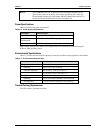
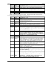
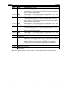
Table 3-3. DMA Map
DMA # Use
0-1, 5, 6, 7
2 Floppy (configurable)
3 LPT 1, only in ECP mode (configurable)
4 DMA 1 cascade
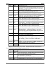
I/O Address Map
Table 3-4. I/O Address Map
Address (hex) Subsystem
0000-000F Primary DMA Controller (#1)
0020-0021 Master Interrupt Controller (#1)
0022-0023 STPC Configuration