


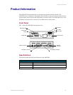

Product Information
2
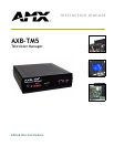
AXB-TM5 Television Manager
Specifications (Cont.)
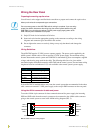
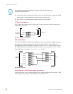
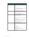
Front Panel Components
AXlink LED AXlink LED (green and blinks to indicate AXlink communication activity and
power:
• Full-Off indicates no power is being received or the controller is not
• functioning properly.
• One blink per second indicates power is active and AXlink communication is
• functioning.
• Full-On indicates there is no AXlink control or activity, but power is on.
Device DIP switch An eight-position DIP switch used to set the AXlink device number for the
AXB-TM5.
Response LED (big red) It can be programmed for flash, full On, and Off modes for control
system responses to local input signals. Refer to the Programming section on
page 9 for programming information.
IR sensor It receives incoming IR signals from a wireless transmitter. Internal high- and
low-frequency (455 kHz or 38 kHz) IR sensors for AMX IR panels.
IR In LED (Red) Flashes when the AXB-TM5 receives an IR signal from a wireless transmitter.
IR Out LED (Red) Flashes when the AXB-TM5 IR port sends an IR command to the television
receiver.
TV Power LED (Red) Lights when the CC-XPS External Frequency Television Scan Sensor detects
power on a television or monitor as the horizontal scanning frequency from the
television receiver.
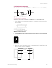
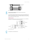
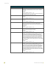
Rear Panel Components
AXlink connector Receives power and information via the AXlink bus and AXlink system
controller.
IR Emitter connector TV sensor connector to detect horizontal scan frequencies from 15 - 65kHz.
Input/Output connector Four TTL input/output ports.
IRX-SM connector Allows for up to eight (parallel) IRX-SM connections.
Optional Accessories • AXB-TM5 control box unit
• CC-XPS scanning frequency sensor with cable
• CC-IRC
IR emitter with cable
• 12 VDC power supply