


Installation and Wiring
5
AXC-232++ RS-232/422/485 Interface Card
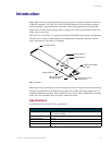
Wiring Devices to the AXC-232++
Card Edge Pinouts
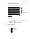
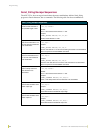
The table below lists the card edge pinouts and the function of each.
Preparing captive wires
To secure wires in a captive-wire connector:
1. Strip 1/4 inch off the wire insulation for all four wires.
2. Tin 2/3 of the exposed wire.
3. Insert each wire into the appropriate captive-wire connector, according to figures 9 through 12.
Insert the wire up to the insulation.
4. Turn the captive screws clockwise to secure the fit in the connector.
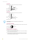
Using RS-232
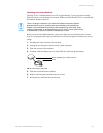
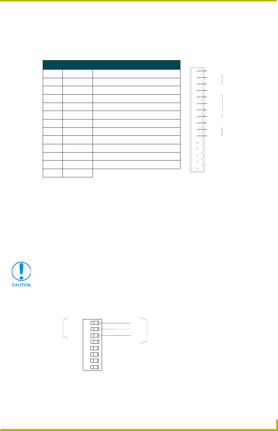
When communicating via RS-232, connect the wiring as shown in FIG. 2.
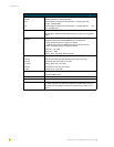
Card Edge Pinouts
Pin Signal Function
1 GND Ground (RS-232)
2 RX Receive data (RS-232)
3 TX Transmit data (RS-232)
4 +12V Power
5 RX - Receive data (RS-422)
6 RX + Receive data (RS-422)
7 TX - Transmit data (RS-422)
8 TX + Transmit data (RS-422)
9 GND Ground
10 CTS Clear-to-send (hardware handshaking)
11 RTS Ready-to-send (hardware handshaking)
12 - 16 Factory Use
If the device is using a separate power supply, do not connect the power wiring from
the AXC-232++ to that device.
FIG. 2 RS-232 wiring
RX
TX
GND
AXB-
232++
Device
TX -
RX +
RX -
TX +
TX
RX
GND
+12V
AXC-
232++
1
2
3
4
5
6
7
8
9
10
11
12
13
14
15
16
GND
RX
TX
+12 V
RX
RX+
TX-
TX+
GND
CTS
RTS
RS-232
RS-422
Hardware Handshaking