


Installation
8
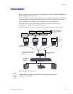
AXR-NWS NetWave Server
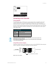
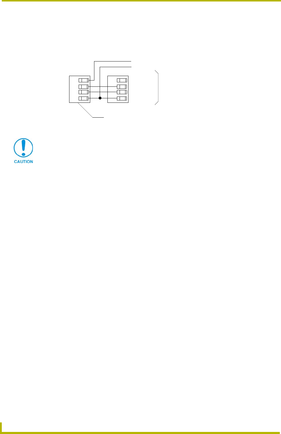
Using AXlink for data with an auxiliary power supply
Connect the Controller’s AXlink connector to the AXlink connector on the rear panel of the AXR-
NWS, as shown in FIG. 6.
Use an auxiliary 12 VDC power supply when the distance between the Central Controller and
Server exceeds the limits described in Wiring Guidelines table. Connect only the GND (-) wire on
the AXlink connector when using an auxiliary 12 VDC power supply.
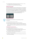
Preparing captive wires
1. Strip 0.25" of wire insulation off the ends of all wires.
2. Insert each wire end into the appropriate opening on the connector according to the wiring
diagrams and connector types described in theUsing AXlink for data and power section on
page 7. Do not tighten the screws excessively; doing so may strip threads and damage the
connector.
Installing the Control System
1. Install the AXR-NWS on any flat surface.
2. Rotate the RF antenna to a vertical position to communicate with the touch panels.
3. Verify that the Server DIP switch settings are configured with the correct GROUP ADDRESS
and GROUP ID.
4. Verify the touch panels have the same GROUP ID value as the Server.
5. Connect the Server to the Central Controller (FIG. 7) by connecting the 3.5 mm 4-pin AXlink
cable from the bus connector to the AXlink connector at the rear of the Central Controller.
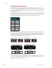
FIG. 6 AXlink and 12 VDC power supply wiring diagram
PWR (+)
AXP
AXM
GND (-)
PWR (+)
AXP
AXM
GND (-)
AXR-NWS (3.5 mm connector)
Controller
PWR (+)
GND (-)
12 VDC power supply
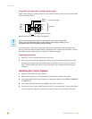
If you are not using power from AXlink, disconnect the wiring from the Controller
before wiring the AXR-NWS. Make sure the auxiliary power supply’s PWR (+) is not
connected to the Central Controller’s AXlink connector.