


For full warranty information, refer to the AMX Instruction Manual(s) associated with your Product(s).
8/06
©2007 AMX. All rights reserved. AMX and the AMX logo are registered trademarks of AMX.
AMX reserves the right to alter specifications without notice at any time.
3000 RESEARCH DRIVE, RICHARDSON, TX 75082 • 800.222.0193 • fax 469.624.7153 • technical support 800.932.6993 • www.amx.com
93-5795 REV: J
Wiring
The Mio Modero uses a four-pin mini AXlink connector for power and data.
Caution: Do not connect power to the Mio Modero until the wiring is complete.
Preparing captive wires
You will need a wire stripper, and flat-blade screwdriver to prepare and connect the
captive wires.
1. Strip 0.25 inch (6.35 mm) of wire insulation off all wires.
2. Insert each wire into the appropriate opening on the connector according to the
wiring diagrams and connector types described in this section.
3. Turn the flat-head screws clockwise to secure the wires in the connector.
Note: Do not over-torque the screws; doing so can bend the seating pins and
damage the connector.
Wiring guidelines
The Mio Modero requires 12 VDC power to operate properly. The necessary power
is supplied via the AXlink cable. The maximum AXlink wiring distance is determined
by power consumption, supplied voltage, and the wire gauge used for the cable. The
following table lists wire sizes and the maximum lengths allowable based on the
maximum power consumption rating of 170 mA.
The maximum wiring lengths for using AXlink power are based on a minimum of 13.5
volts available. If the distance is greater than what is listed in the table, consult the
Mio Modero Device Family Instruction Manual for wiring with external power sources.
Connecting the Wiring
Caution: If using power from AXlink, disconnect the wiring from the control system
before wiring the Mio Modero.
AXlink Data and Power Connections
Connect the control system's AXlink connector to the AXlink connector on the rear
panel of the Mio Modero for data and 12 VDC power as shown in FIG. 4.
Mounting Procedures
AMX recommends mounting the Mio Modero in a standard one-gang wallbox, a
conduit box per NEC specs section 370, with a minimum internal clearance of 2-5/8"
x 1-3/4" x 1-5/8" (HWD), but it is possible to mount the Mio Modero to a podium
without a wallbox. More installation details are available in the Mio Modero Device
Family instruction manual.
Wallbox Mounting
1. Use the cutout dimension for the wallbox to cutout the install surface for the
Mio Modero.
2. Confirm that the terminal end of the AXlink cable is disconnected, and not
receiving power.
3. If the faceplate is connected to the mounting frame, place a flathead screw-
driver in the notch at the bottom right of the Mio Modero, and pry the faceplate
from the mounting frame.
4. Connect the AXlink power supply. The connector passes through the center of
the mounting frame and connects to the board. The connection is illustrated in
FIG. 2.
5. Place the mounting frame on the wallbox; align the screw holes with the mount-
ing holes on the panel, and fasten the mounting frame to the wallbox using the
screws supplied.
Note: Do not overtighten the screws when mounting the mounting frame. The device
should be flush with mounting surface.
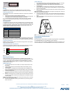
6. Attach the faceplate to the mounting frame first at the top and swing it to the
bottom. See FIG. 5
Podium Mounting
1. The necessary area for the mounting frame opening is 2.00 x 2.25; cutout the
mounting frame install surface to accommodate the Mio Modero.
2. Confirm that the terminal end of the AXlink cable is disconnected, and not
receiving power.
3. If the faceplate is connected to the mounting frame, place a flathead screw-
driver in the notch at the bottom right of the Mio Modero, and pry the faceplate
from the mounting frame.
4. With the mounting frame resting in the cutout area, drill the mounting holes into
the flat surface.
Note: Do not overtighten the screws when mounting the mounting frame. The device
should be flush with mounting surface.
5. Connect the AXlink power supply. The connector passes through the center of
the mounting frame and connects to the board. The connection is illustrated in
FIG. 2.
6. Attach the faceplate to the mounting frame first at the top and swing it to the
bottom. See FIG. 5.
Programming The Mio Modero
KeypadBuilder
Most functionality of the Mio Modero is handled using the application, KeypadBuilder.
Go to www.amx.com for the KeypadBuilder Instruction Manual.
There are a select number or SEND_COMMANDs the Mio Modero recognizes. For a
full list and descriptions, consult the Mio Modero Device Family Instruction Manual.
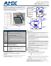
FIG. 3
Example Device DIP Switch set to 129
Wiring Guidelines at 170 mA
Wire Size Maximum Wiring Length
18 AWG 690.42 feet (210.43 m)
20 AWG 436.80 feet (133.13 m)
22 AWG 272.33 feet (83.00 m)
24 AWG 171.66 feet (52.32 m)
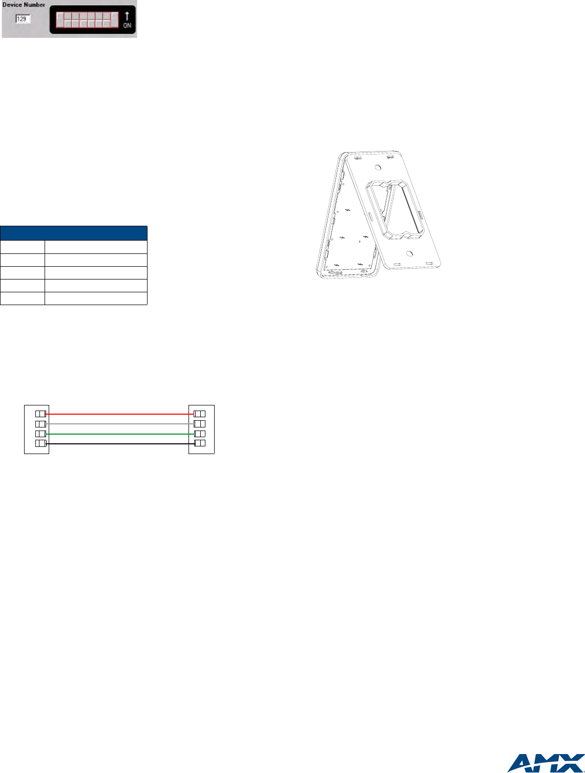
FIG. 4 AXlink wiring
PWR +
AXP
AXM
GND -
PWR +
AXP
AXM
GND -
Mio Modero Control System
FIG. 5 Attaching the faceplate to the mounting frame